

Introduction: High Five Collector


In this basic wearables project, you will build a circuit to collect high fives. The final circuit is a simple one you can learn to build in my free Instructables Wearable Electronics Class (Digital Input and Digital Output lessons).
You will need:
- LilyPad Arduino (or similar) microcontroller
- USB cord
- Computer with Arduino software and USB port
- alligator leads
- sewable LED
- LiPo Battery
- Handmade switch with conductive fabric
- Conductive thread
- Multimeter (optional)
- Paper
- Pen
- Pencil
- Felt
- Fabric marker
- Soft measuring tape
- Fabric glue (Fabri-Tac)
- Ruler
- Straight pins
- Sew-on snaps
- All-purpose thread
- Hand sewing needle
- Scissors
- Heat 'n' Bond
- Iron & ironing board
- Sticky back Velcro tape
- Fabric paint
- Hot glue gun with glue stick
- Small piece of parchment paper
- Penny-size piece of polyester filling (optional)
- Small scrap of white fabric (optional)
- Fusible interfacing (optional)
Step 1: Build Circuit


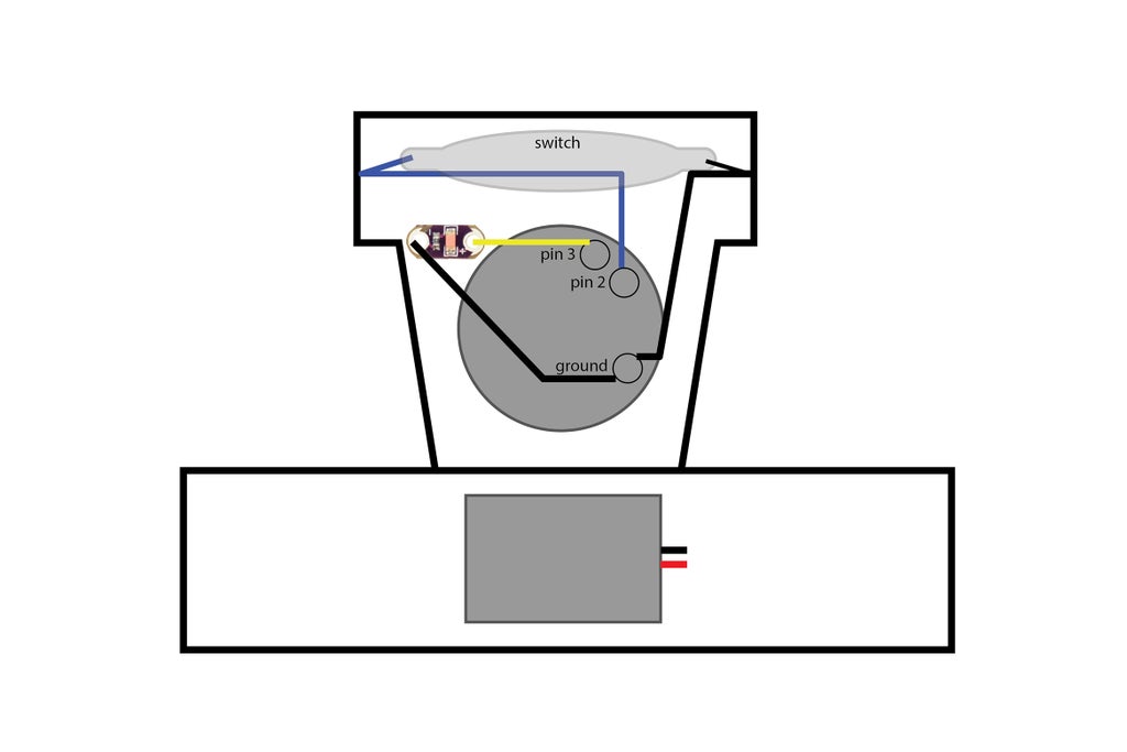
Connect the circuit as illustrated.
handmade switch --> pin 2
handmade switch --> ground (-)
LED power (+) --> pin 3
LED ground (-) --> ground (-)
Step 2: Upload Code

Download the attached sketch and upload it to your board. The LED will blink twice then stay on. This means that the sketch has loaded and is running.
How Does it Work?
When the sketch loads and is running the switch listens to see if there are any switch presses. Open the serial monitor to watch the switch presses.
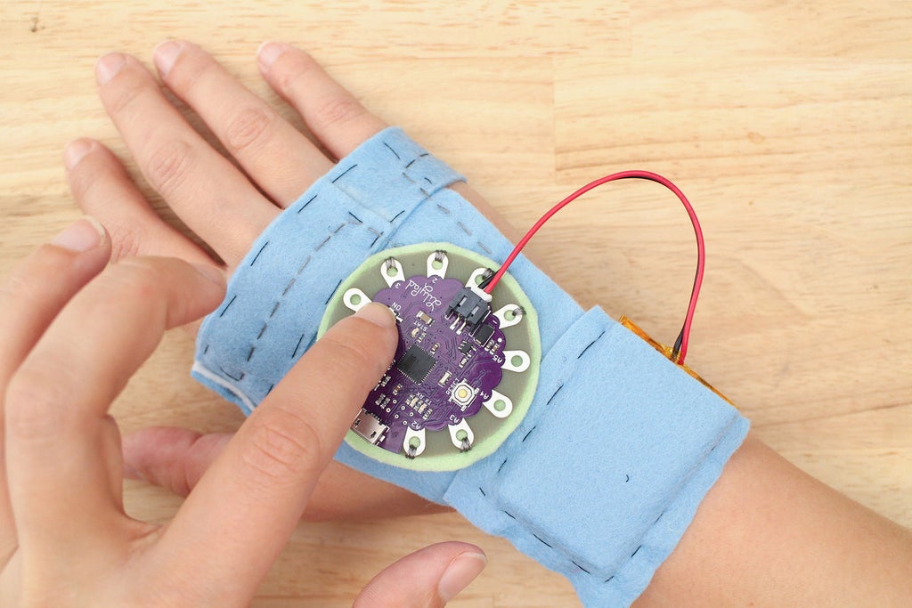
Go ahead and press your switch! The LED will go off and that one press will be recorded in the software. Press the switch four more times and the LED will go on, indicating you have reached five presses. Press it another five times, it will go off and come back on when you reach 10. This is how it collects high-fives, it records how many times the button has been pressed and lets you know what you have reached your goal.
Put the switch on and give a high-five to test it out!
Variables are created to hold the number of times the switch is pressed, the current state of the switch (on/off) and one to hold the previous state of the switch. The previous state gets stored because it is compared to the current state later in the sketch.
int buttonPushCounter = 0;
int buttonState = 0;
int lastButtonState = 0;
This is where the previous state of the switch gets compared to the current state. The != characters mean not equal to. If the buttonState variable value (1 or 0) is not equal to the lastButtonState, check to see if it's LOW (0/pressed). If it's LOW, increment the count of switch presses (high-fives) and store it in the variable buttonPushCounter. The block of code that gets executed also prints the current value of the buttonPushCounter, so you can see it's progression.
 if (buttonState != lastButtonState) {
    if (buttonState == LOW) {
      // if the current state is LOW then the button
      // went from off to on.
      // if the state has changed, increment the counter
      buttonPushCounter++;
      //print that the button is pressed/on
      Serial.println("on");
      //print the number of pushes you are on
      Serial.print("number of button pushes:  ");
      Serial.println(buttonPushCounter);
    }
The modulo - %, divides one number by another number and leaves the remainder. Here it is dividing the buttonPushCounter variable value by five and asking if the remainder equals zero. The remainder will only equal zero when the value of buttonPushCounter is zero or a number evenly divisible by 5, like 5 ,10, 25, etc. If the division of the buttonPushCounter by five equals zero, the LED goes HIGH and turns on. If it does not equal zero, the LED is LOW and remains off. Try changing the five to a higher number to collect more high-fives.
if (buttonPushCounter % 5 == 1) {
    digitalWrite(ledPin, HIGH);
  } else {
    digitalWrite(ledPin, LOW);
  }
Attachments

Step 3: Make It Mobile

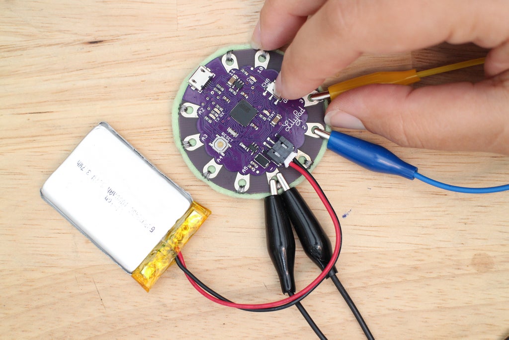
When plugged into the computer through USB, the LilyPad board receives power. To power the board while it's not connected to the computer you use the LiPo battery.
Unplug the USB cord from the board and grab your LiPo battery and plug it into the JST connector on the board. Push the switch towards ON to power the board. Your project is now mobile and can go anywhere! To charge the LiPo battery, keep the board connected to the computer via USB and push the switch towards CHG.

Give a high-five or clap your hands 5 times to see the LED light up. Snap a photo of your switch working with a battery and upload it below!
Step 4: Record Connections & Disconnect


After the final circuit is built and tested with the sketch it is ready to transfer onto fabric. To do this, the circuit needs to be unclipped and taken apart. To know how to put the circuit back together it needs to be recorded. There are three ways you can do this that I will briefly go over now:
1) Draw a schematic diagram. I find this to be a fun process because learning how to read schematics is like learning how to decode secret messages coupled with reading a map. In a schematic diagram, each electrical component is represented by a graphic symbol. Check out this instructable of How to Read Circuit Diagrams for an introduction to schematic symbols. The Electronic Symbol page on Wikipedia is also a good place to start.
2) Create your own drawing. Use a pencil or computer to create a diagram of your own making. Mark the pin numbers on the microcontroller and the power and ground of each component. Draw in the traces and you have your own roadmap of which to rebuild your circuit by.
3) Write it down. For simple circuits, you can write down each connection line-by-line. For example:
high-five switch --> pin 2 of LilyPad
high-five switch --> ground of LilyPad
No matter what method you go with, always double check the recording to make sure you wrote the connections down correctly.
Once you have recorded the circuit, you are ready to safely take the circuit off the alligator leads. After you disconnect everything, you will have four components:
1 x LiPo battery
1 x LilyPad USB
1 x sewable LED
1 x handmade switch
In the next step, we will build the accessory this circuit will be sewn to!
Step 5: Make a Simple Pattern

The design is part glove and part bracelet. I've decided that it is a kind of mitt, so when I reference "the mitt", I am talking about the final project. :)
Fabric is the main substrate you'll use when creating wearable electronics. This fabric can come in two different forms:
1) A project that is cut and sewn together from yardage, often using a pattern
2) An already sewn garment that you augment

They both have their pros and cons. In this project, you will create your own pattern from scratch. When prototyping, creating your own piece gives you more control and introduces you to the process of making a custom accessory using fabric.

First, grab the soft measuring tape and take some measurements. Write down the measurements from the three places illustrated above.
1) Across the knuckles
2) Length of back of hand from knuckles to wrist
3) Circumference of wrist
The final pattern consists of 3 pattern pieces:
1) Back of hand
2) Wrist strap
3) Handmade switch with strap
One and two are created using the measurements taken in the previous step. Number three you already created in the Introducing the Switch lesson. Grab a fabric marker and a ruler and draft these two pattern pieces:

Back of Hand
For this simple pattern, it's ok to draw straight onto the fabric. You are welcome to make a paper pattern for future use. Use the fabric marker to draw out the three measurements you took on a piece of felt as pictured. Add .25" to each measurement. Remember it's easier to cut away from fabric than it is to add more.
Wrist Strap
Create a rectangle 1.75" wide x wrist circumference. Add 1" to the length measurement to create an overlapping closure. The LiPo battery will be attached to the wrist strap in a later lesson, so check to see that the LiPo battery will fit within the dimensions before moving on. Adjust the 1.75" width to fit if necessary.
I've attached my final patterns for these two pieces.
Attachments
Step 6: Fit & Sew

Cut out both the back of the hand and the wrist strap patterns. Pin them together and place over the hand to get a feel for how the pieces size up. The top of the trapezoid should cover your knuckles and the wrist strap should comfortably be able to wrap around your wrist. If the pieces are too large, trim them back. If they end up being a little too small, it's best to cut them out again with added length.
Pin the switch to the top of the trapezoid, leaving one side loose.

Time to try it on! Pin the switch strap around your hand and the bottom strap around your wrist.


The only strap that you need to make adjustable is the wrist one. This means you need to fit the switch on snugly because you won't be able to adjust it later.
Test the switch with the multimeter on the continuity setting as it's pinned to get the right fit.
Once it's pinned, you will most likely see some bulges or buckling of fabric. If this occurs, unpin, tuck in extra fabric and pin in place. If working one handed proves to be difficult grab a friend to help you.


Grab a needle and thread because you are ready to sew your connections. Use a basting stitch to join the trapezoid and wrist strap.

Stitch the switch strap in place. Great job! You have created and fitted a custom pattern! Try it on one last time, is the switch strap too loose? Is it too snug? How is the length of the trapezoid? Test the switch with the multimeter again to hear it beep while closed.

Step 7: Draw Circuit on Fabric

You have your final circuit working with the sketch and you've finished sewing your fabric pattern. Now is the time to combine the two and put the circuit onto the fabric.
Component list for Hi-5 Collector:
1 x LilyPad USB
1 x sewable LED
1 x LiPo battery
1 x soft switch
The switch is already embedded in the pattern, so you don't have to worry about placing it. Clip the battery into the JST connector on the LilyPad USB. Place the components on top of the trapezoid to see how they all lay in relation to one another. Take this moment to finalize where the components and microcontroller will be.
Things to take into consideration when placing your components:
1) Visualize your conductive paths. When possible, do not put a component in a place that will create paths that cross one another.
2) Leave room to sew down and around components
3) Are any components polarized?
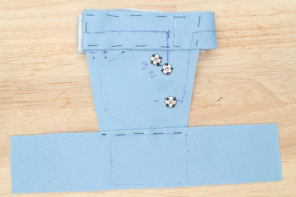
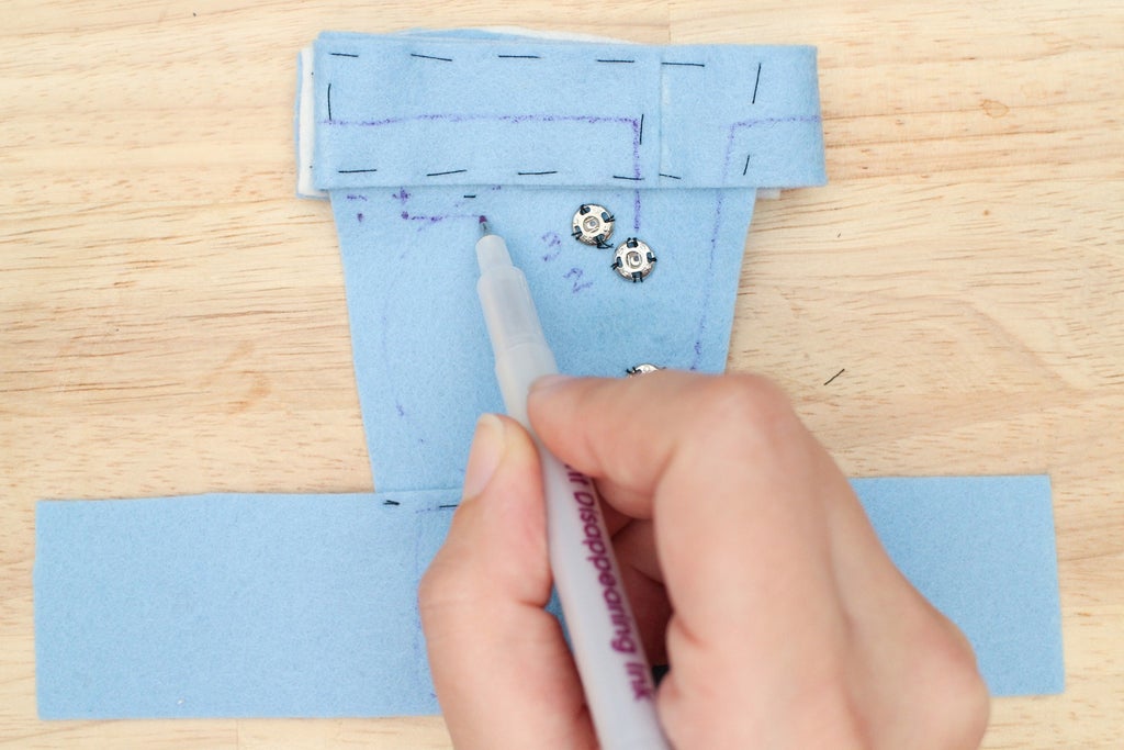
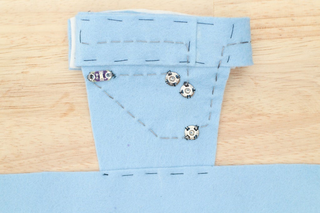
Follow the attached diagram or experiment with the placement. The marking tool isn't permanent, so you can draw the placement and circuit as many times as you like!

Use the fabric pen to trace around the battery, LilyPad USB and LED. Make a dot through each hole of the LED and mark the ground (-) and power (+) side.

In the Making Connections + Modularitylesson of my free Wearable Electronics class, you can learn to sew snaps onto the back of your microcontroller so it could be removed from projects later on. Now is when you sew the other half of those snaps to your project. You do this before drawing in the traces because you will be connecting the components to them. Remember, connecting components to the snaps are the same as connecting them directly the microcontroller pins.
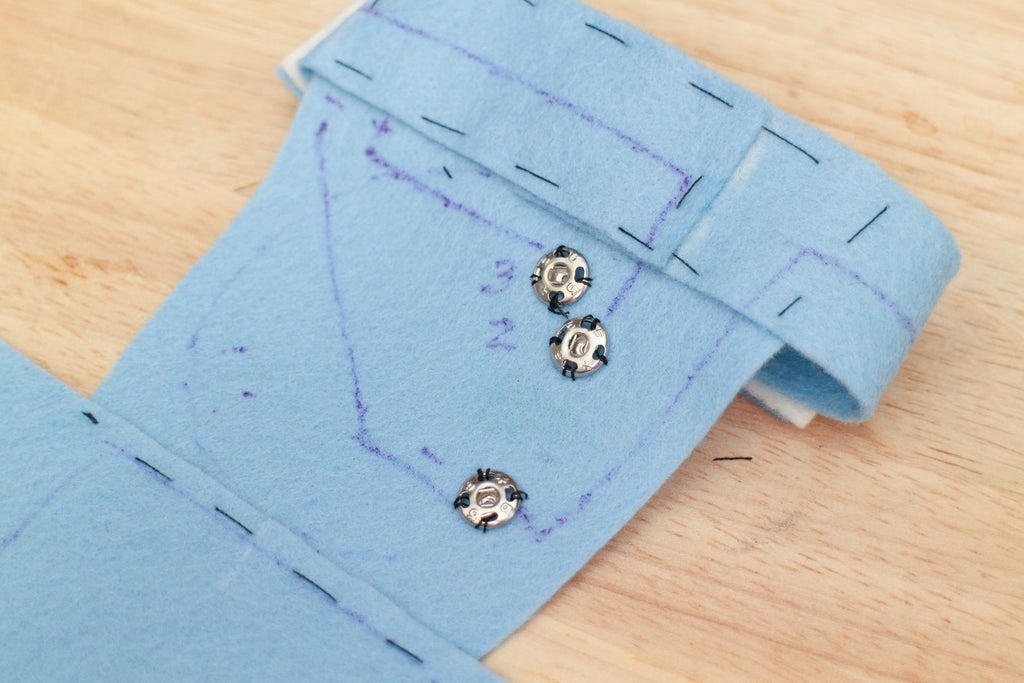
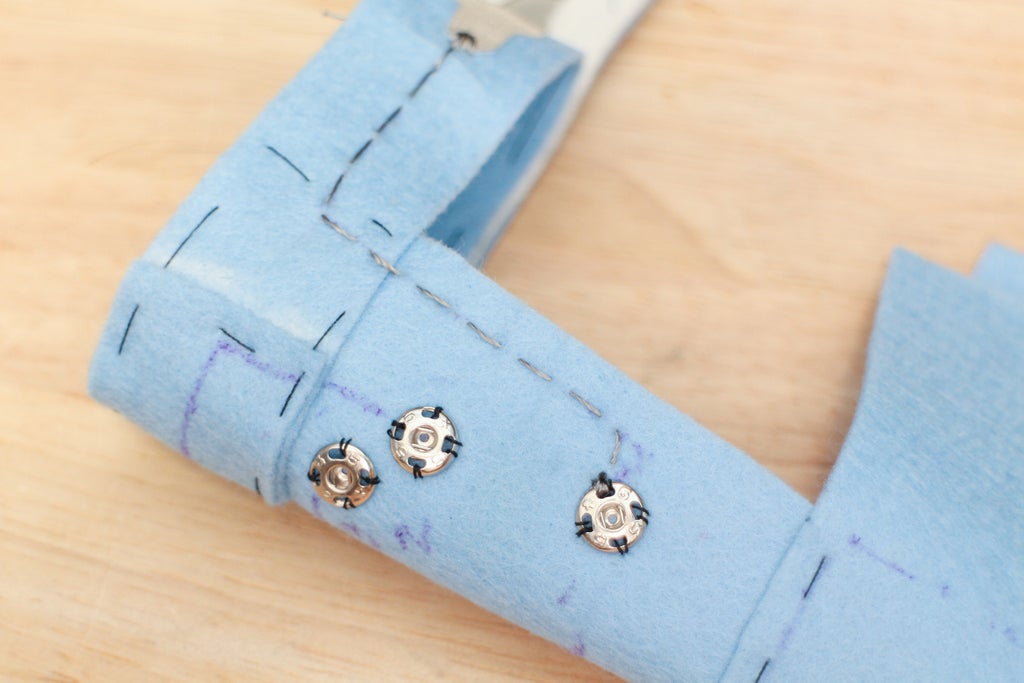
Look at where the center of each snap hits the fabric on pin 2, 3 and ground (-) and make a dot.
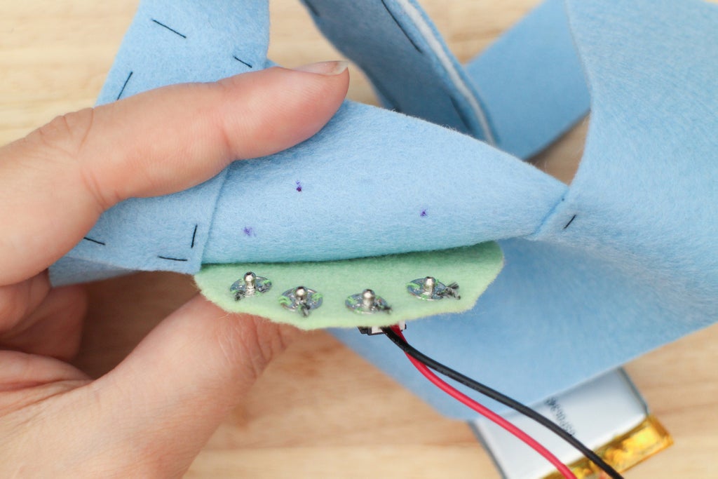

Center each snap over the marks and sew down using regular thread. Label each snap with its corresponding pin so you know which is which.

Draw the first trace from the switch lead to a hole on the ground (-) snap. I tend to draw traces straight and create corners when I need to change direction. Feel free to get creative with your lines.
Draw the remaining connections:
Remaining side of switch to pin 2
Power (+) side of LED to pin 3
Ground (-) side of LED to ground (-) snap.
Notice how the trace going from the ground of the LED to the ground snap travels inside the board's outline. The shortest distance between two components may be under another component. That's ok as long as you do not create a short. If the exposed conductive trace touches two exposed metal parts on the bottom of the LilyPad USB, that would create a short. To prevent one, simply look under the component you would like to make a trace under and check for exposed areas and see if the path you create will cross it. If you find that it will, use some electrical tape to cover the exposed parts on the board, or find another path between the two components.
Step 8: Sew Conductive Traces

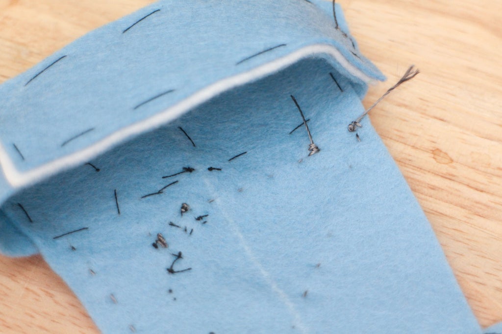
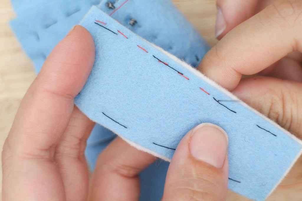
The uneven running stitch stitch is the same as the running stitch except every other stitch is shorter than the other. I find it useful in wearable electronics when I want to minimize the amount of conductive thread exposed on one side. This side is usually the inside of a garment or accessory that touches the skin.
If you are working with fabric that has some thickness, like the felt, the exposure can be minimized further by only picking up the top of the fabric as you make the shorter stitch.
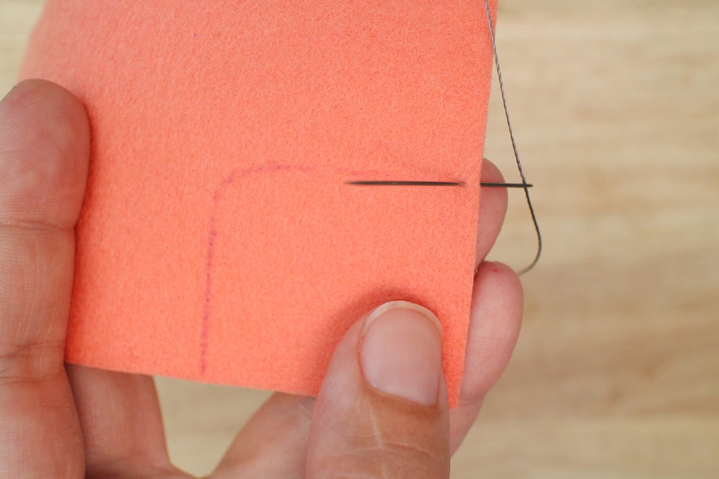
Poke the needle through the front, from the back to start the first stitch.
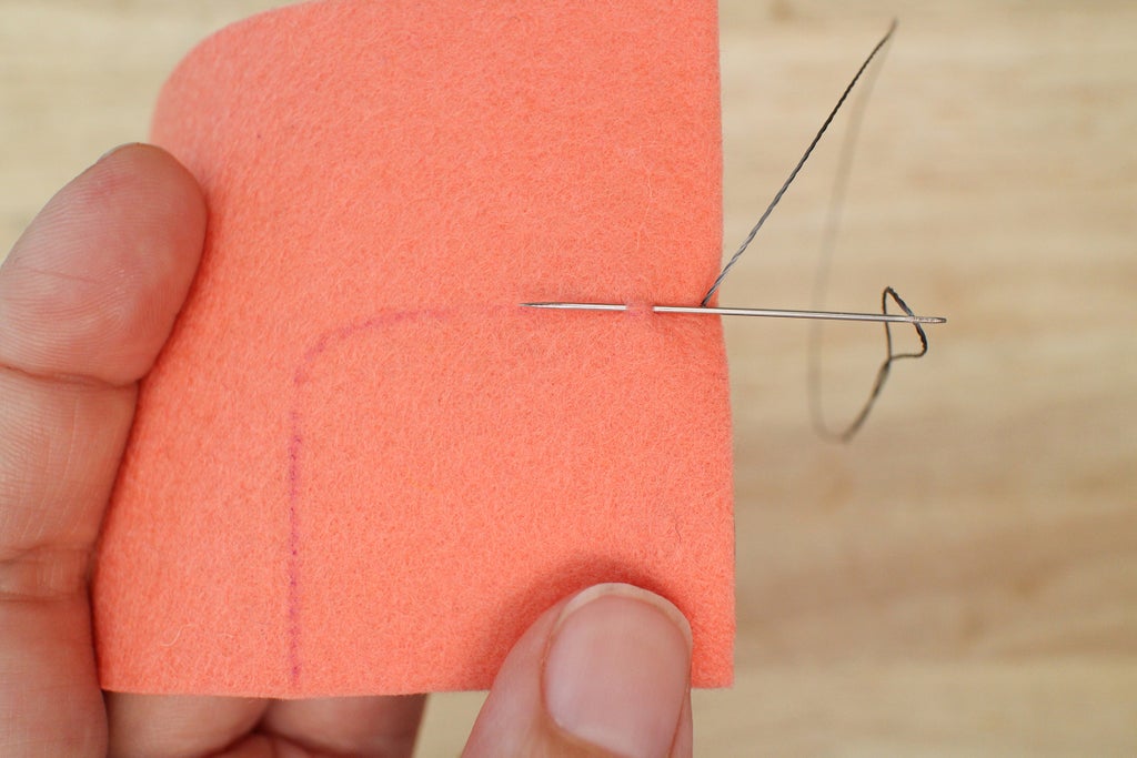
Pierce through the top of the felt to create the shorter stitch.
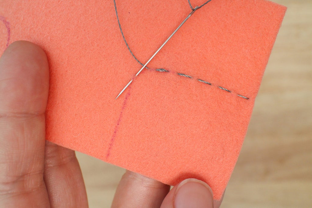
Pick up just the top if the felt.
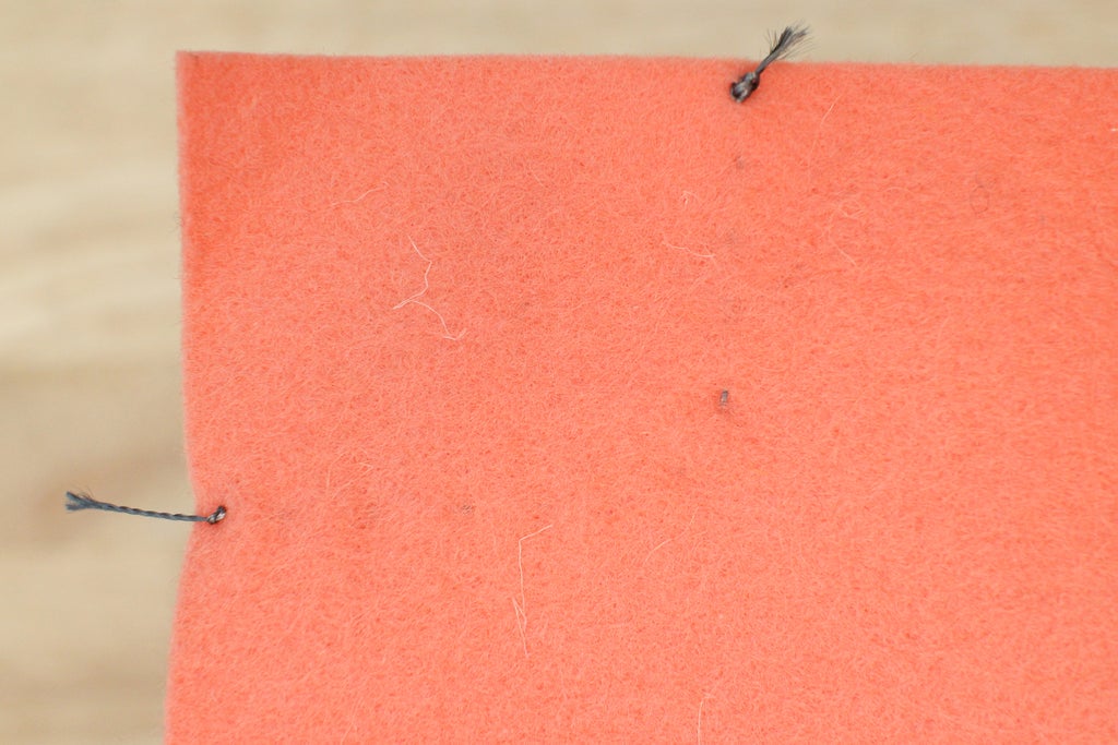
View from the back showing how the thread doesn't pierce through to the back completely.

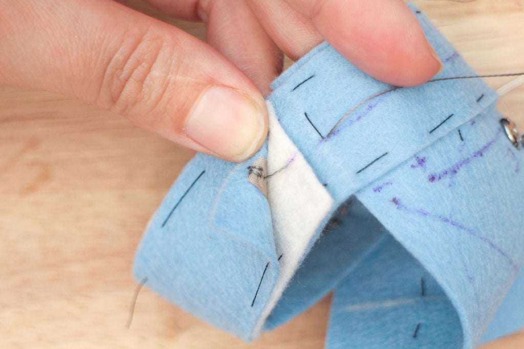
Thread the needle with conductive thread and knot the end. Using the uneven running stitch, sew the trace between the ground snap and the switch first. Do this by sewing through the lead of the switch and following the drawn line to the ground snap. Finish with at least 3 stitches going through the hole of the snap. Use the uneven running stitch for the rest of traces. Finish and knot all the traces on the back.
Sew the other side of the switch to the pin 2 snap.
Sew the LED power (+) to pin 3 snap.
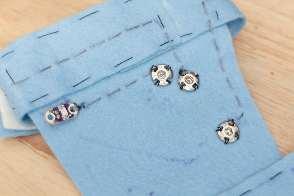
Sew LED ground (-) to ground snap.
 Turn the project around. Tighten the knots up, put some glue on them and wait for them to dry. Cut off all the tails and you are done!
Step 9: Battery Pocket


The circuit is ready to get powered and mobile! Next it's time to sew a pocket for your battery to fit into. The basting stitch will also come out and be replaced with a running stitch to make the sewn connections stronger.
You are now ready to give mobile power to your project. For this to happen, the LiPo battery needs a place to stay on the project. A simple pocket works great to hold it snugly in place and allows for it to be removed when you need to wash the accessory.
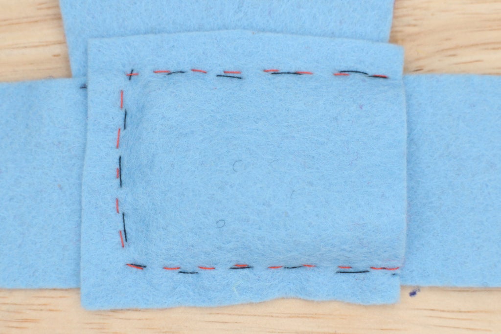
Cut out a rectangular piece of felt measuring 2.5" x 2.25". The edges should measure .5" past the edge of the battery on three sides.
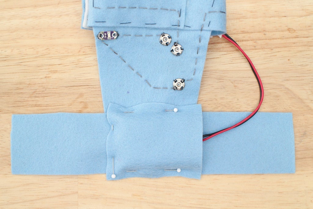
Put the battery in place and lay the fabric on top. Smooth the pocket down the sides of the battery and pin where they hit the fabric. It's ok if the two corners pucker a little.
So you know how snug you are making the pocket, keep the battery in as you stitch. Sew the pocket down using a basting stitch and smooth the two puckers at the corners out as you go.

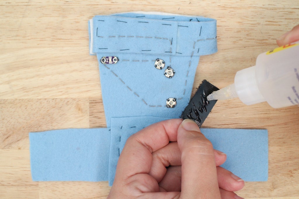
For the wrist strap closure, apply some Fabri-Tac to two pieces of velcro that match the width of the strap. Place the two pieces so they fasten where the strap overlaps.

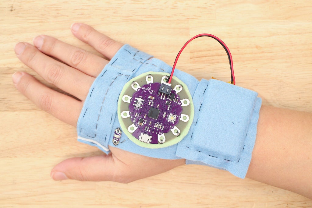
Now, for the final fit! You've done a lot of fits by now, which is a good habit to get in when creating something wearable. Snap the LilyPad USB on and plug the battery in. How does it feel? Make sure to snap a photo and share it below!

Push the power switch on the LilyPad USB towards ON. If everything is good, the LED will flash two times then stay on. This indicates that the sketch is running and it's ready to receive high-fives. It's time to test the sewn circuit and how good of a job the switch does at capturing high-fives.
Find someone and give them a high-five. Did the LED turn off? If it did, that's a good sign. If it did not, try high-fiving again. The mitt counts how many times the switch closes up to five, then starts counting again. With every fifth high-five the LED will turn on, telling you that's how many you have collected.
If you are having problems, do not worry! Troubleshooting is a large and necessary part of building electronic circuits.
Troubleshooting Guide
LED is not flashing after the board is turned on.
- Did the program upload correctly? Check in the Arduino IDE and see if you received an error.
- Is the LED sewn in the right direction? Even when you double check the polarity of an LED, they can sometimes get turned around. Look to see if the LED ground (-) is connected to the LilyPad ground(-) and power (+) to power (+).
LED turns on prematurely or behaves erratically.
- Look for a short between the LED's power and ground.
- Test the switch in the Arduino IDE using Serial.println() to print the switch's state in the serial window. Watch the switch state print out to see if the switch is being pressed without giving a high-five.
Is something still not working right? Don't panic! Let me know what you are having trouble with in the comments below and we will work it out together.
The basting stitch is a temporary stitch used to hold things in place until you know they are where you like them. At this point, it's time to remove the basting stitches and replace them with something stronger - the running stitch.
Slip on the mitt and test the fit of the switch one more time.
If You Need to Make the Strap Larger or Smaller
Mark where the strap ends on the back of your hand and take out all the basting stitches before you start sewing. After the basting stitches are all out, place the overlapping end of the switch strap either to the right (smaller) or to the left (larger) of the mark the amount you need to adjust for.
If Everything Fits Great
Thread a needle with 18" of regular thread. Start making a running stitch along the edge of the switch. Be careful to not pierce through the basting stitches, this makes them harder to remove. Knot and cut when done when you run out of thread.
When you are done replacing all the basting stitches grab a pair of scissors and snip a basting stitch. Start removing the basting stitches by pulling them out with your fingers or the blunt end of your seam ripper. The loose stitches will come out easily. Keep removing them until the mitt is basting stitch free.


You are almost there! Replace the basting stitches around the pocket.


Step 10: Insulating Circuit & Diffusing the LED

Soft circuits use conductive materials that are not insulated. That's why when you finish creating a circuit, it is sometimes a good idea to cover it up to prevent shorts and to help protect it from weathering over time. There are several ways you can do this.
In this step, I go over three different ways to protect a soft circuit and two different ways to diffuse an LED. You will follow along step-by-step as I use a few different methods.

Fusible interfacing is usually used as structure in collars and button plackets when making clothing. It comes in many weights and can be knitted (stretchy!), woven or non-woven.
Because it's and iron-on material and can be found in any fabric store it makes for a convenient way to cover up exposed circuits. To use it, first identify the side with the adhesive. This is usually the side that feels rough. Draw and cut out a shape that will cover the conductive material you would like to protect. Sometimes interfacing is translucent enough to see the circuit through so you don't have to guess the size and shape of the cover. If you can not see through it, cutting it in strips and building as you go works well.


There are lots of different kinds of fabric paint out there to try. For this project, I chose the kind you can squeeze from a tube. This is sometimes called "puffy" or "3D" fabric paint. The applicator bottle makes it great for covering a single stitched line which is why it's a great choice for this project.


Heat 'n' Bond is a material I love to use while creating prototypes and it comes in handy when covering wearable electronics. It's a hot-melt adhesive film that can be ironed onto a fabric that you want to become iron-on itself. One side is paper and the other is the adhesive. Before using it you need to identify the adhesive side which is the shiny side.
Heat up an iron to med-high heat. Place the adhesive side down onto the fabric you wish to make iron-on. Place the hot iron on top of the paper and apply heat. Stay there for a second and then slowly move onto the next area. Apply enough heat until the adhesive sticks to the fabric and then let it cool completely. You now have iron-on fabric!
When you are ready to use it simply peel off the paper backing, place the fabric adhesive side down, and iron it down. The paper is useful for drawing designs on before cutting shapes out and ironing.


Now that you have been introduced to three ways you can easily cover your exposed circuits let's apply two of these methods to the Hi-5 Collector.
Covering conductive thread traces will protect them from shorts, abrasion and general weathering over time. What material you choose to cover your traces with will determine what level of protection your circuit will have in those three departments. You material choice will also affect:
+ the thickness of the final project
+ how the fabric drapes after the circuits are covered
+ the overall aesthetic of the project
+ water resistance
I chose fabric paint for this project because it's light weight and the application bottle makes it very easy to apply to a single stitch line. Blue and red is a favorite color combination of mine, so the fact is was red also lured me in.
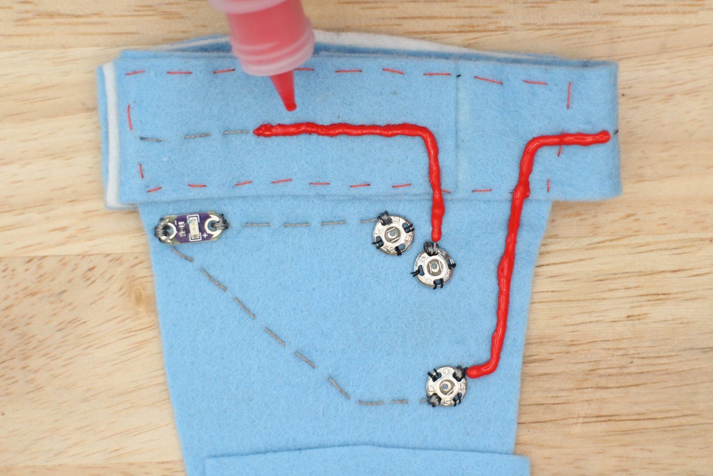
Remove the microcontroller and battery so they are out of the way. It helps to start the paint flow over another piece of fabric. It can start flowing too quick and catch you by surprise which leads to an unsightly blob at the beginning of a line. Take the fabric paint and start drawing over each trace, covering the circuit completely.


You have now covered the front of the circuit, but when using conductive thread you also need to address the back of the circuit where the stitches may have poked through. At this point, the knots are already covered with glue, but if any stitches broke out to the other side you may need to cover those.
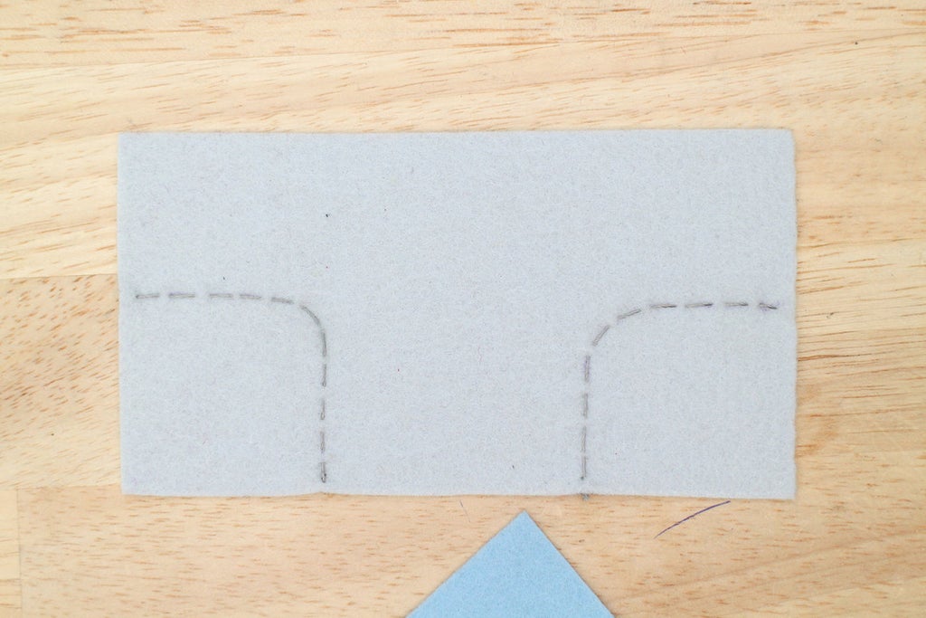
If covering a small amount, you can use glue to cover the remaining circuit but we also want the inside, the part that touches the skin, to feel soft. Ironing on a fabric layer will protect any exposed threads and give a soft and even feel when against the skin.
Iron some Heat 'n' Bond to a piece of felt. If you want specific instructions on how to do this, go back to the Covering a Circuit:Iron-on Fabric step in this lesson.

Turn the project inside out. Trace the trapezoid shape (where the circuit is sewn) onto the paper and cut out. You now have a trapezoid shaped iron-on patch! Peel the paper backing off the trapezoid and place it, adhesive side down, on the back of the circuit.


Iron the patch on with the iron set to med-high heat.


Use the iron-on fabric to cover an remaining exposed thread.

LEDs are fun to use, but sometimes you want them to go beyond a point of light. To take away hard shadows and lines an LED produces, you can diffuse it. Diffusion is achieved by placing a material on top of an LED that spreads and softens the light, taking it from a point of light to illuminating a larger surface area. You can use many materials, such as silk, acrylic, and flexible polymers. I'm going to show you how to diffuse an LED using two different materials that you can pick up from your local craft store.
Polyester Filling
Also known as Poly-Fil or polyester stuffing. This is the soft fluffy material you use for pillows and stuffed animals. You can also use batting, which is a sheet of polyester or cotton fibers pressed and tangled together to make a lofty sheet. Batting is usually used for quilting and upholstery, but can be pulled apart and used for diffusion as well.
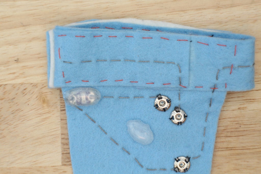
If you put a layer of polyester filling over an LED it does wonders in the diffusion department. Its softness also makes it perfect for wearable projects. If using polyester filling for diffusion, finish it off with a small piece of white fabric. Cut a shape that fits over the amount of filling covering the LED. Sew around the edges of the fabric using a straight stitch to create a soft bubble. To clean up the appearance of the fabric edges cut out a ring of felt and glue that on to cover the raw edges and stitched line.

LED without diffusion.

LED with poly filling.
Hot Glue
Using hot glue is a favorite of mine, yes it's crafty, cheap and can be messy. But when you are making something that is not a product, it can be exactly what you need. This is the method I chose for the final project and will teach you how to do in the next steps.

LED without diffusion.

LED with hot glue.

To diffuse the LED with hot glue you make a sort of lens that gets placed on top. There are a couple different ways to make this lens. You can make a separate lens that gets attached to the LED later, or you can hot glue right onto the LED its board.
I will show you how to make a separate lens that gets attached to the LED. You can hot glue right over the LED if you like but if I need to remove it later I find it easier to if it's made separately, then attached.
Plug in your hot glue. Put some parchment paper on top of the LED. When your glue gun is hot, cover the whole LED and a little past the edge all the way around.

Make multiple lens playing with size and shape.

After the hot glue hardens peel the designs off the parchment paper.

Try on the different sizes and choose one that you like. You want one that extends a little past the outer edge of the LED.

When you put the hot glue lens on top of the LED you will notice a gap between it and the felt. This is easily fixed by hot gluing around the LED board to create a wall for the lens to sit on top of.
Heat up the hot glue gun and put a layer of glue on the felt around the board. One layer should do it. Once the glue hardens, put another thin layer of hot glue down.

Lay the lens on top of the wall and hold down until it hardens.


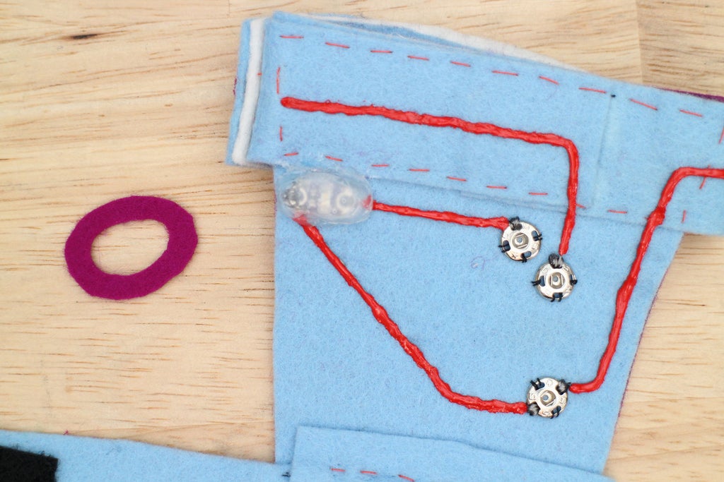
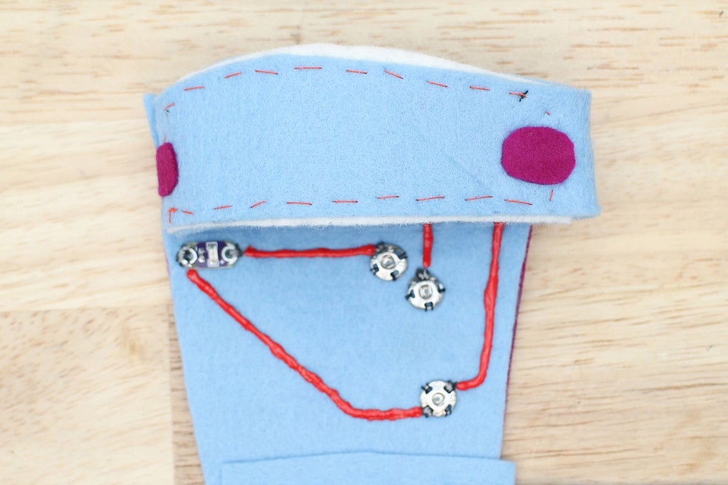
The lens may look a little rough around the edges. To clean them up cut an oval ring of felt the same size as the lens. Apply some Fabri-Tac to the back and press it into place. This will give a more finished look to the LED and hot glue lens.


Remember to always test after a step of progress has been made! Snap the LilyPad USB on and plug the battery in. Put the mitt on and push the power switch to ON. Give some high-fives to test to see if everything is still working.
Is something not working correctly? Try these things first:
+ Check to see the LilyPad USB is snapped to the correct pins.
+ Charge the battery
+ Connect the board to the Arduino IDE and open the serial window to see if the switch is closing when you give a high-five.
Still having problems? Comment below and we will solve it together!
Step 11: Wear It!
Congratulations! You are officially done with the Hi-5 Collector and now you can get out there and start getting your high-fives [insert party popper emoji here]. I hope you have enjoyed building this project. You can now program an Arduino compatible board, sew a running stitch and design soft switches for all kinds of fun actions.
If you liked this project, check out more in my free Wearable Electronics Class as well as classes on Arduino, Raspberry Pi, Internet of Things, and more!
Show off your finished Hi-5 Collector below!


