

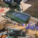
Introduction: How to Choose Carbon Tubes for Your Skateboard Frame


Hi All
Two weeks ago, we calculated the loads for our skateboard frame, last week we reviewed the numbers and decided on carbon fiber tubes as the building blocks for our frame. Today we are going to choose the actual tubes that will do the job.
The loads that we apply to the structure are balanced by the internal stresses which are created inside, this happens because everything should be in balance. Stresses have the units of force divided by area. The higher the applied loads, the higher are the stresses, the bigger and beefier the structure, the smaller the stresses are. Why is this important? We can calculate the stresses. Once we know the stress levels, we can choose the appropriate materials and dimensions for our purposes. Each material has the stress levels that it can accept (allowable) and the stress level at which it breaks (fracture). Whatever we choose, we need to verify that the existing stress levels are lower than the fracture stress.
Is this all? Not quite. As with all real-world problems the final solution is a compromise between several requirements. We cannot make everyone happy, but we can design a solution that will satisfy all the requirements, and eventually everyone will almost be happy . So, what is there besides the stresses? There are also safety factors, stiffness, and the resulting mass. We will deal with each one of these.
Step 1: Safety Factors

What is a safety factor?
Imagine you are designing a park bench. You did all your calculations, verification, testing and you have built it. You have chosen your structure and materials in a way that the maximum load that it can bear is 200 kg, meaning it breaks at around 200.1 kg. This was your goal and you are happy with the result. You take your bench to the park, put it in the designated spot, and you place a big sign that says: “Maximum load – 100 kg”. You have just created a factor of safety (FS) of 2. FS is the ratio between the fracture stress/load and the existing stress/load. Why would we use these factors? The reason is that it accounts for all of the things we don’t know. Although we do our best with estimating loads and choosing correct material properties, there are always uncertainties and things that we are not aware of. In order to design and create despite these uncertainties, we implement safety factors. What is the down side? It is usually the resulting mass of the structure. Higher safety factors will require more material and therefore more mass. Important thing to remember is that safety factors are design requirements. In our everyday life, we can find the lowest required safety factors in the aerospace industry, where mass is extremely important. The highest safety factors are in civil engineering, where you can always use another ton or two of concrete to make the building stronger.
Step 2: Stiffness and the Total Mass
What about stiffness? We regard stiffness as the “springiness” of the structure. Do you remember playing with springs at the science class? The spring will expand or compress when you apply force on it. In our case it is the elastic deflection, or bowing, of the frame when we stand on it. Stiffness is defined as the ratio between the applied load and the resultant deflection. Why is this important? If we know what deflection we are comfortable with, we can design the structure in a way for it to meet this requirement. We don’t want too flexible frame – it will be very uncomfortable to ride, on the other hand too stiff structure is also undesirable – we will feel every bump on the road. An interesting thing to do is to use this property in order to eliminate dampers on the final product, the elasticity of the frame will be our damper, with zero additional cost and no added mass.
And the resulting mass? Well, we aim for the lightest solution possible, together with satisfying the other requirements.
Step 3: Our Requirements and Carbon Fiber Properties


Now it is a good time to define our design requirements, we aim for the following:
- Three parallel tubes as the main deck. (Ver.0 for reference).
- Standard sizes for the tubes.
- Minimum safety factor of 2 to fracture.
- Deflection in the middle of the frame of no more than 30mm under maximum load.
- Minimum mass.
First let us understand the material properties of carbon tubes. Standard tubes are made by numerous manufacturers, but the fibers themselves are sourced from relatively few manufacturers. One of the leading world manufacturers is Toray from Japan. T300 is the fiber type that is manufactured by Toray, and it is by far the most widespread and known fiber in the world. There is a high chance that any standard carbon fiber tube that you look at will be produced out of T300 with 3k tow count. Let's look at the properties of this fiber. Notice there are two sections in the data sheet: for the fibers themselves and the composite material. We are interested in the latter. Notice that these are lower than the pure fiber because of the added epoxy.
The numbers in the data sheet are the ideal properties, they cannot be guaranteed by any manufacturer. In order to be on the safe side, we will knock down these properties by 30% - this is usually very realistic.
There are two numbers that we are interested in from the above table – Tensile Strength, which is the fracture stress, and Tensile Modulus, which is the elasticity property of the material. Rest of the numbers will be relevant later. After the knock down we get the following numbers: 125 kg/mm^2 for fracture stress and 9276 kg/mm^2 for elasticity modulus.
Step 4: Loads and Cross Section


For the calculation of stresses, we will consider the following numbers from our Case 1:
L=86cm=860mm – length of the frame
M=25.9 kg.m – Max. bending moment
V=60 kg – Max. shear force
We derived them here.
By considering the longest frame, we will be on the safe side with any variation of loads and frame length.
What is the most important thing when looking for a structure that will support loads? It is the cross-section. The cross-section is simply the area and the shape which is obtained once we "cut" the structure. In our case, for the tube, we see a ring with inside diameter (ID) and outside diameter (OD).
With known diameters we can calculate two important values: the area of the cross-section: A, and the moment of inertia: I. See formulas with pictures.
Area is simple, but what is the moment of inertia? This value tells us how resistant the cross-section to bending, in other words – what is the geometry stiffness to bending. If you take a simple steel ruler for example, it is very easy to bend it in one direction (thickness), and almost impossible in the second one (width). The reason is that the width direction has much bigger moment of inertia.
Now it is time to calculate some stresses. Bending and shear stress formulas are attached in the images. The deflection is calculated with formula from "Roark's Formulas for Stress and Strain".
Step 5: Results

Let us look at the table above.
First of all, why are these diameters? These are the standard sizes that we can find from different manufacturers. The advantage is obvious, it is a readily available product and there are no additional development costs.
If we look from top to bottom – small diameter tubes to large diameter, we can see that the first two will not satisfy our requirements for safety factor or stiffness or both. The smallest diameter tube that will satisfy both of our requirements is the third one: OD=18mm, ID=14mm.
Of course the bigger tubes will also work, but they are bigger and hence heavier. Note also that they are much stiffer and we don’t want that. The best news is that these three tubes together will weight less than 400 gr!
Congratulations, we have chosen the carbon tubes that we will use!
Next time we will see what can be done with the end units of the frame.
Please visit us and subscribe to our mailing list.
Link to the original post.
Enjoy,
Dani


