Introduction: IOT BIT GSM V1.5 Hat for the Raspberry Pi
IOT BIT is the ultimate HAT that makes your Raspberry Pi truly useful anywhere. Our intelligent HAT module provides GSM Mobile Data for the Raspberry Pi, GPS positioning information and Bluetooth connectivity. This is the perfect module for hackers, scientists, and creators as it gives your Pi powerful connectivity wherever you are. Simply plug our module into your Raspberry Pi and start playing.
The HAT can integrate easily with the software on your operating system giving you access to general internet data through the mobile network. Using our API this hat gives you the ability to send SMS (text) messages and communicate over Bluetooth. We also give easy access to the GPS onboard which exposes location data.
HAT Features:
- Supports any micro sim, just slot your sim card in and get going.
- Easy set-up, with a single terminal command, setup our software to streamline IOT BIT with your Raspberry Pi.
- GSM Mobile Data for the Raspberry Pi.Battery support.
- Wake up your Pi or trigger events with text messages.
- Optional external antenna for better reception.
- High-efficiency power regulation up to 3 amps.
Step 1: Whats in the Box?
Package includes:
- 1 x GSM Board
- 1 x GPS antenna
- 1 x signal antenna
- 1 x Bluetooth antenna
- 1 x USB cable to micro USB
- 1 Link to instructions
Step 2: 40-Pin Header Layout
The schematic of the 40-Pin header to fit your project accordingly with the available pins.
Step 3: Put IoT Bit Together With the Raspberry Pi
- Raspberry Pi wall plug Into IOT BIT to power both IOT BIT and Raspberry Pi.
( You don't need to also plug in the Raspberry Pi). - Put the 2 antennas and the GPS antenna into IOT BIT.
- Place the Sim card into the IOT BIT simcard holder with the cut corner facing away from the board(which you can buy from any major sim provider )
Step 4: Setting Up the Raspberry Pi
Components needed for the Raspberry Pi to be operational:
- Raspberry Pi 2 or 3.
- Monitor.
- Mouse and keyboard.
- HDMI Cable.
- Raspberry Pi Charger.
- SD card (more than 8GB is required) with the latest version of Raspbian Jessie.
The guide to setup the Raspberry Pi software can be found at https://www.raspberrypi.org/learning/hardware-gui...
The latest version of the Raspbian Jessie can be found at https://www.raspberrypi.org/learning/hardware-gui...
Step 5: IoT Bit Easy Setup
There are multiple ways to get this up and running. The first is to download the disk image and flash it using Win32 Disk Imager. You will need an SD card that is 8GB or bigger. The link for the download is below: http://download.altitude.tech/
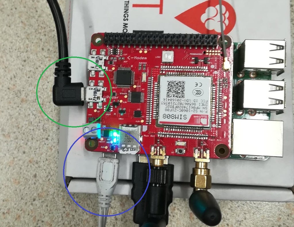
To use turn on the IoT Bit by plugging in the power cable to the USB port labeled POWER. Once connected the IoT Bit will power the Raspberry Pi.
Also, you can use IOT BIT on a windows system. All you have to do is use these drivers and install them: http://download.altitude.tech/IoT%20Bit%20Windows...
Step 6: Functions of LEDs
POWER (Green) - This Led should be on when the IoT Bit is connected via USB when the IoT Bit is powered via battery this led will be off.
CHARGE (Blue) - Led is on when the IoT Bit is connected via USB when the IoT Bit is powered via battery this led will be off. This Led also works as an indicator when the battery is fully charged. If the IoT Bit is connected via USB and the battery is connected too. Once the battery is charged this Led will turn off.
ACTIVITY (Blue) - Turns on in startup when is off it means the modem is ready for use.
NET (Blue) -when it turns on shows that the IoT Bit is reading the sim card, when this led is blinking fast it means that is looking for a signal lock, when it starts blinking slowly it means it has locked to the provider of the Simcard.
RGB Led - This LED will turn White at the start meaning that the board is not connected to the modem USB, then the activity light will turn on the RGB will flash green and then blue, the activity and the RGB will turn off meaning the modem is ready for use.
Step 7: Enable the UART Bus
The IOTBit GSM HAT does not have a USB COM port interface, therefore, we will use UART to communicate with it. So we need to enable UART on the Raspberry pi. We will be working with a RPi 3 so the instructions below are specifically for this version. If you are using an older version of the raspberry pi please contact us for further support.
This can be done in two ways:
First, you can use our bash script which can be found here https://github.com/Altitude-Tech/IOTBit_GSM
remember to give it executable permissions by doing :
$ chmod +x Uart_Enable_RPi3.sh
Then run it by doing:
$ sudo ./Uart_Enable_RPi3.sh
Secondly, you can do it manually following the below steps.
- Make a backup of your current system just in case anything goes wrong!!!
- Open up terminal and type
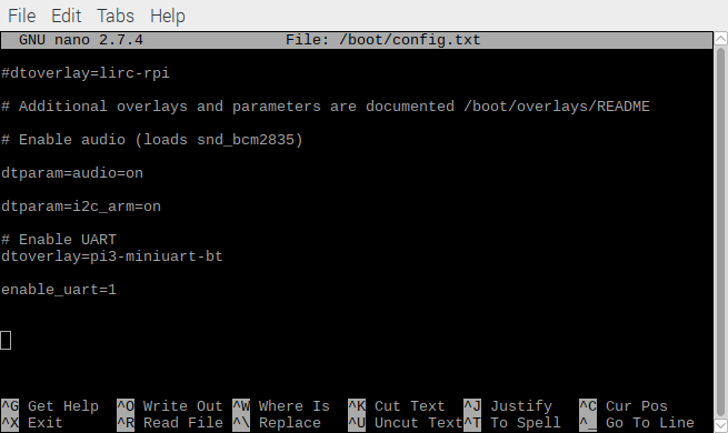
- $ sudo nano /boot/config.txt
- add the following to the file
- enable_uart=1
dtoverlay=pi-miniuart-bt

- Save the file use ctrl-x then y and enter.
- Next open up the cmdline.txt file using the following command.
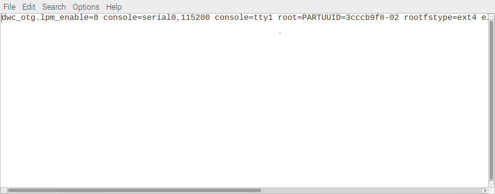
- $ sudo nano /boot/cmdline.txt
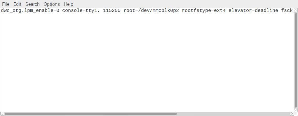
- Modify the file so the contents are the same as the second line.:
dwc_otg.lpm_enable=0 console=serial0,115200 console=tty1 root=/dev/mmcblk0p2 rootfstype=ext4 elevator=deadline rootwait

dwc_otg.lpm_enable=0 console=tty1 root=/dev/mmcblk0p2 rootfstype=ext4 elevator=deadline rootwait

- Now reboot the system
- Once you have rebooted the UART bus should be enabled.
- To test this use:
- $ sudo apt-get install minicom
- $ minicom -D /dev/serial0
Depending on you version of Raspbian your UART port will either be ttyAMA0, ttyS0 or serial0. If you are using Rasbian stretch it will be serial0.
- You should see modem ready continuously repeated.

Step 8: Updating Firmware
This step is required since there has been a new update recently. Once UART has been enabled we are ready to upload the new firmware. ATTENTION, It is important at this stage, before continuing, to power the IoT Bit and the Raspberry Pi independently to do this step.
Navigate to the IOTBit-GSM_Firmware_Update folder you can download it from https://github.com/Altitude-Tech/IOTBit_GSM
Using terminal do:
$ cd ~/IOTBit-GSM_Firmware_Update
$ sudo python Firmware_Updater_IOT.py
The script will ask you for the serial port if you are using Raspbian stretch and above you can input /dev/serial0
If the upload is successful the program will write and read from multiple memory addresses then say verification ok

Step 9: Instructions of Use
To use the board simply download the Example_Script.py and the IOTBit_Library_GSM_Variant.py from the GitHub repo: https://github.com/Altitude-Tech/IOTBit_GSM
From the example script, you can test basically any AT commands replacing the "AT+CPIN?" by your command, more AT commands for the SIM808 can be found in the pdf attached in the same GitHub repo.


