Introduction: Interactive Cylindrical Cube
This is a creative cylindrical LED cube with proximity sensing by infrared led and photo-transistors. Interactive Cylindrical Cube includes: 8X8 royal blue LEDs, 12 infrared LEDs, 16 photo-transistors and all of them are bent & formed a cylindrical shape.
Please see video below when this interactive cylindrical cube is used as flowerpot.
Step 1: Bill of Material
Step 2: Project Schematic
You can download high resolution version at link: Interactive Cylindrical Cube Schematic
Step 3: Assembly and Soldering
- Cylindrical cube arrangement:
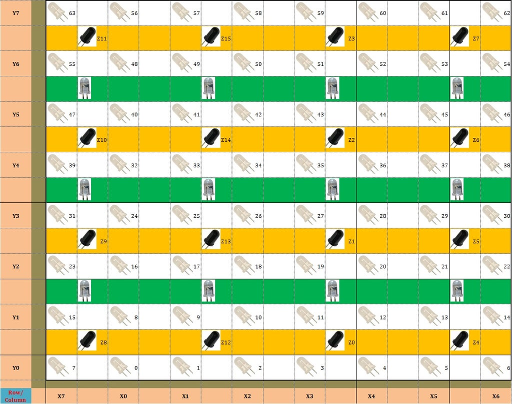
Let see the picture above to understand how to arrange Leds - Phototransistors - Infrared Leds.
- Yellow row: photo-transistors (x16 pcs), Common - Collector type with with RE ~ 10Kohm.
- Green color: infrared Leds (x12 pcs), connect to 5V with current limit resistor 100 ~ 150 ohm.
- White color: royal blue LED (x64 pcs), with current limit resistor 100 ohm.

- Build a cylindrical led 8x8:
In order to arrange leds in cylindrical form, I used a flat wooden template with LED spacing 20mm. And after all leds were soldered, I bent them to a cylindrical shape of 50mm inside diameter and 80mm outside diameter.
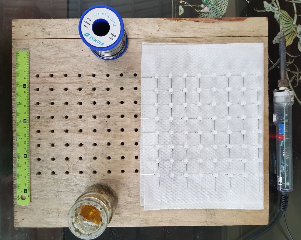
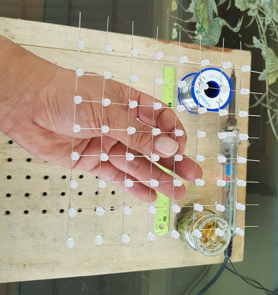
TIP: I used a PVC pipe with 50mm diameter and bent it slowly following this shape, then using a wooden template to fix the first column of leds while soldering last column and first column together.
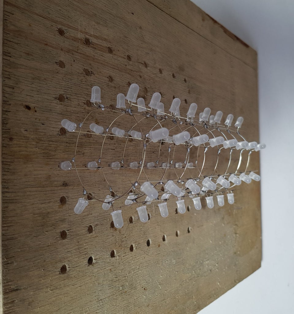
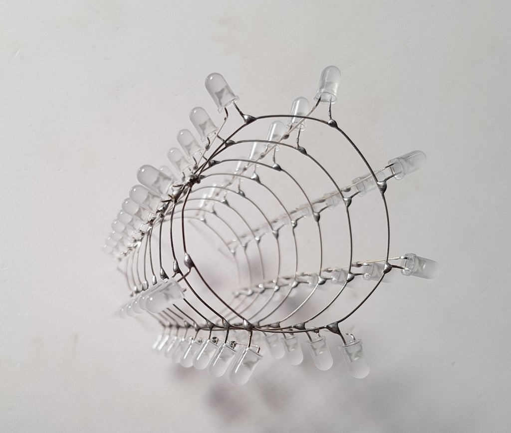
- Build IR led and photo-transistors circuit:
Picture below is shown how to solder IR leds & photo-transistor circuit. I reused the led's wooden template to arrange the IR leds (white led) and photo-transistors (look like black led), note that 4 analog output pins of the photo-transistors should be arranged cleverly.
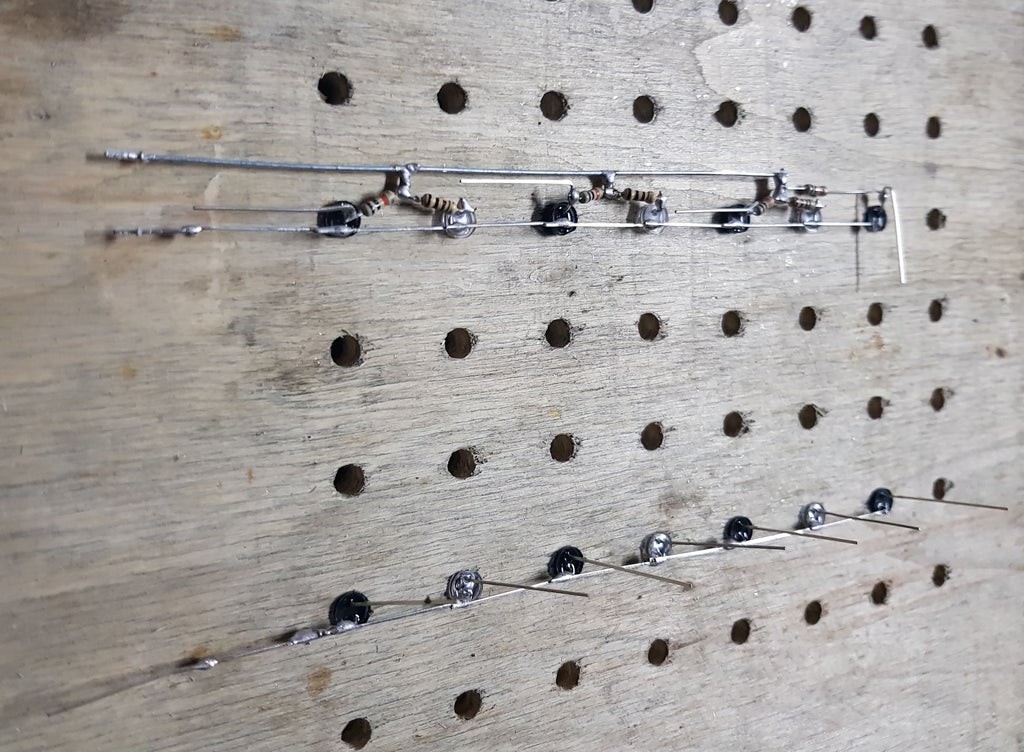
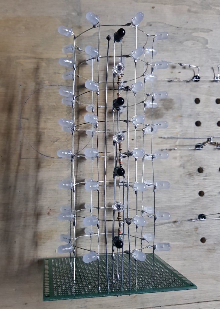
Soldering cylindrical led and IR led - phototransistors to DIY Prototype PCB base.
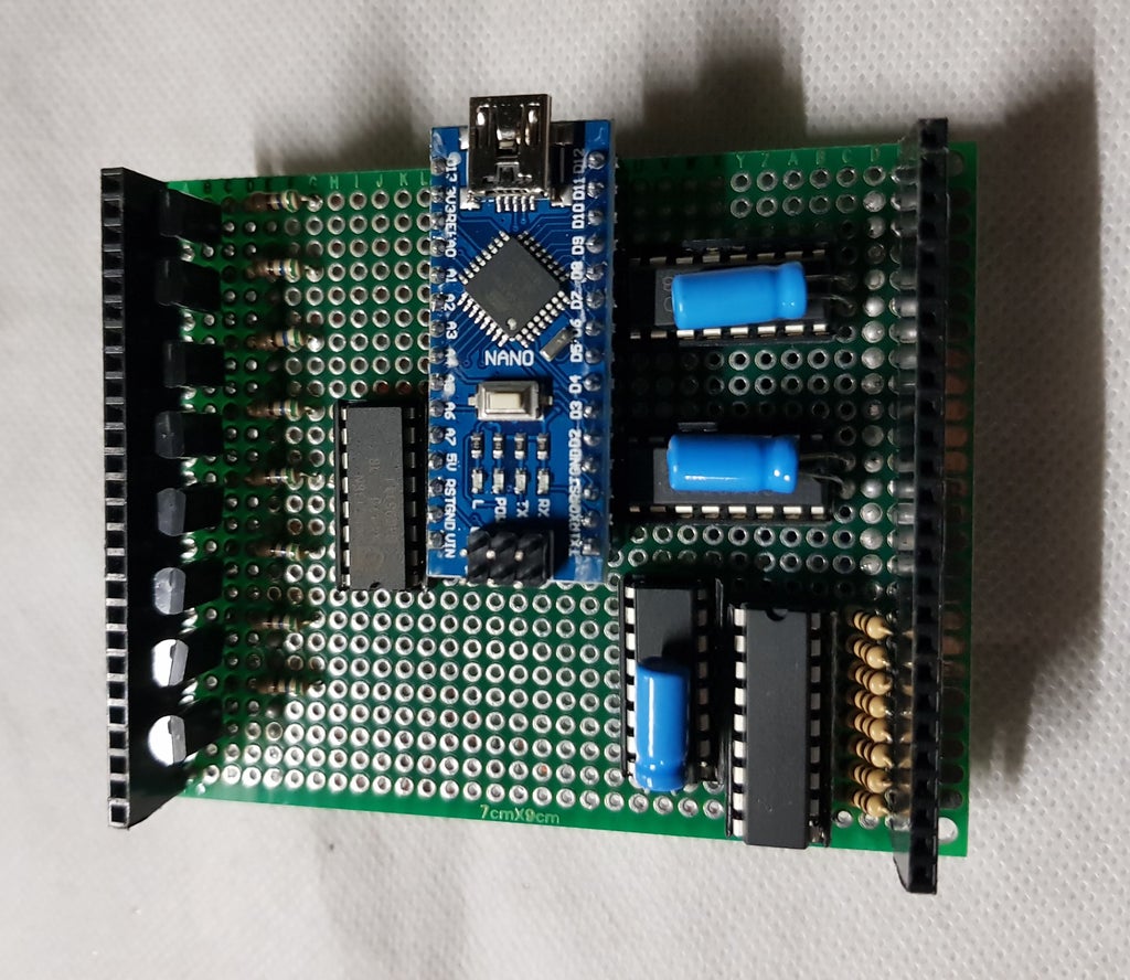
- Build a control board:

Following schematic above to solder the control board
- Finish interactive cylindrical cube
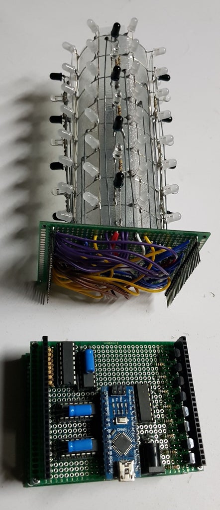

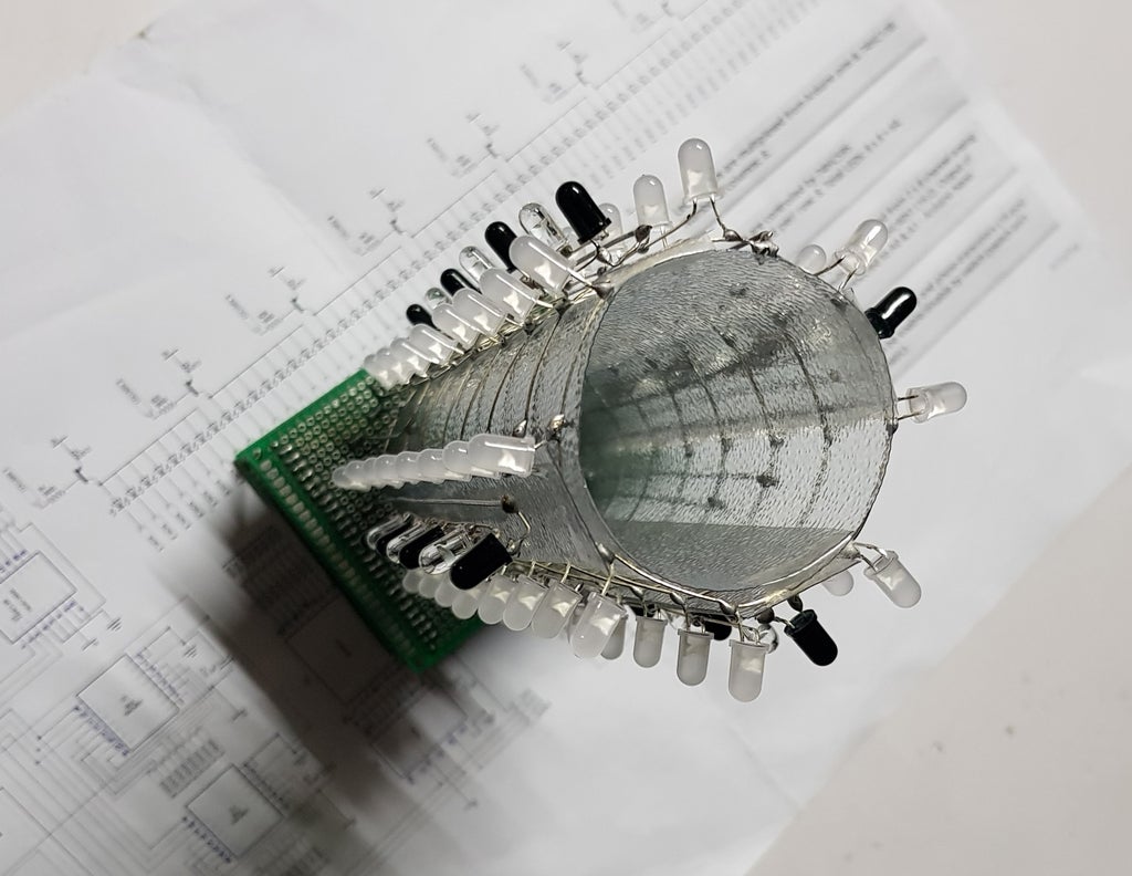
- Build cover box
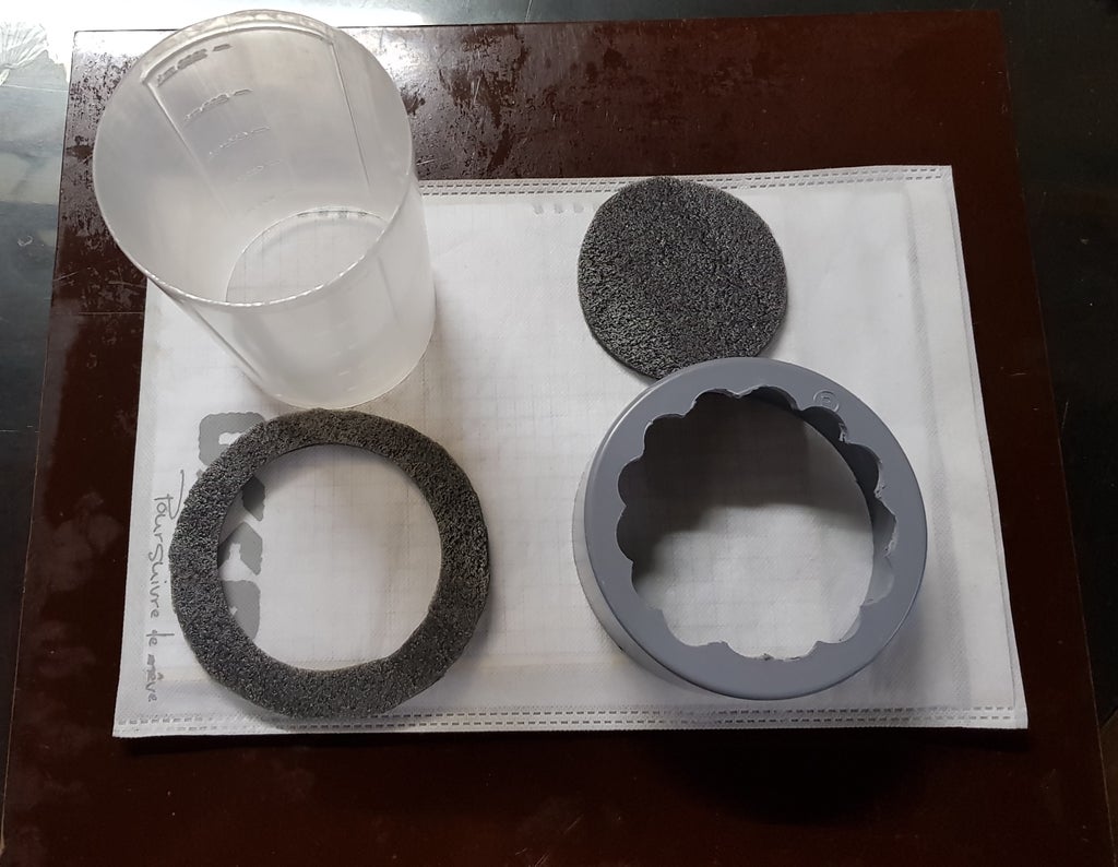
I reused one portable bottle, clear color with diameter 90mm, height 160mm and end cap of PVC pipe diameter 114mm to make a box cover.
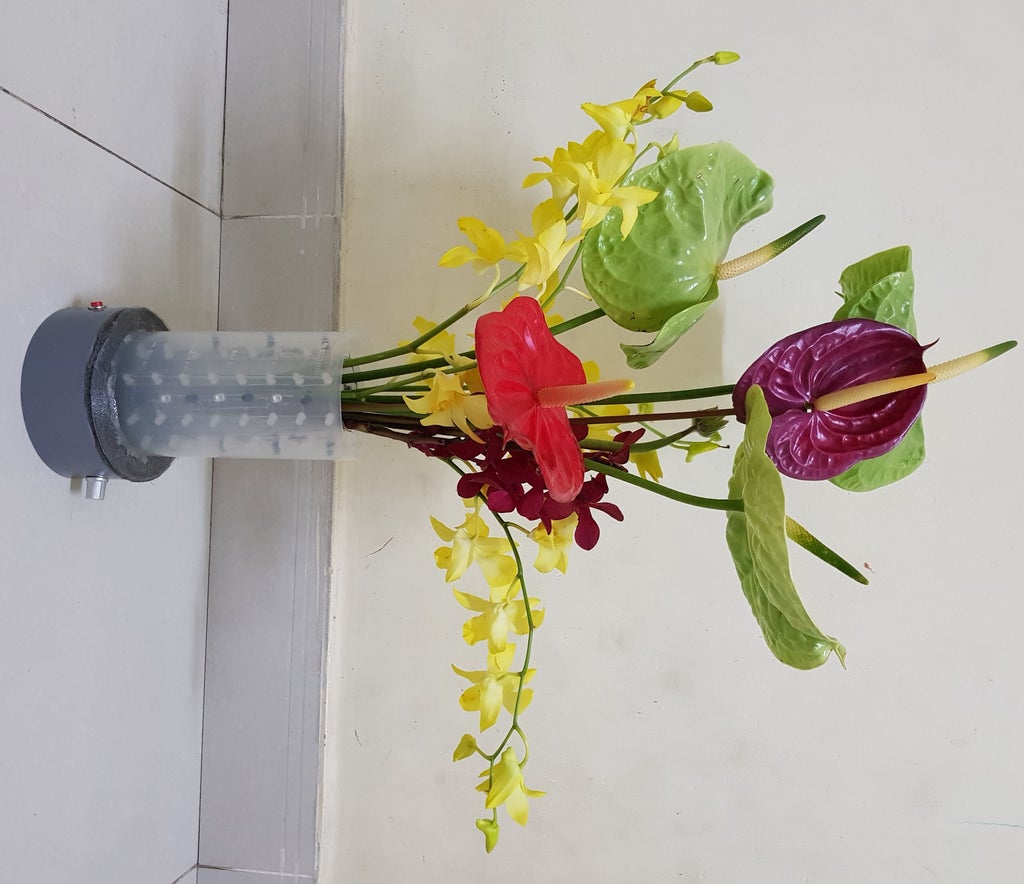
 I also added a push button and a potentiometer for further adjustment, ex:change working mode/ adjust the phototransistor response time/ fading time. Finally, I bought some flowers for decorating and testing.
Step 4: Programming
See the red cell on picture above, it represent for the 16 photo-transistors, marked from Zone00 to Zone15 and around each zone, we have 4 LEDs correspondingly.
Example: Zone00[4][2] = {{3, 0}, {4, 0}, {3, 1}, {4, 1}}; It tells us that photo-transistor number 0 is read by A0 pin of Arduino Nano and around it is 4 LEDs with coordinates: {6, 0}, {7, 0}, {6}, { 7, 1}. When photo-transistor receives infrared ray higher than presetting value (ProximityValue), corresponding 4 LEDs will be turned on.
byte Zone00[4][2] = {{3, 0}, {4, 0}, {3, 1}, {4, 1}};
byte Zone01[4][2] = {{3, 2}, {4, 2}, {3, 3}, {4, 3}};
byte Zone02[4][2] = {{3, 4}, {4, 4}, {3, 5}, {4, 5}};
byte Zone03[4][2] = {{3, 6}, {4, 6}, {3, 7}, {4, 7}};
byte Zone04[4][2] = {{5, 0}, {6, 0}, {5, 1}, {6, 1}};
byte Zone05[4][2] = {{5, 2}, {6, 2}, {5, 3}, {6, 3}};
byte Zone06[4][2] = {{5, 4}, {6, 4}, {5, 5}, {6, 5}};
byte Zone07[4][2] = {{5, 6}, {6, 6}, {5, 7}, {6, 7}};
byte Zone08[4][2] = {{7, 0}, {0, 0}, {7, 1}, {0, 1}};
byte Zone09[4][2] = {{7, 2}, {0, 2}, {7, 3}, {0, 3}};
byte Zone10[4][2] = {{7, 4}, {0, 4}, {7, 5}, {0, 5}};
byte Zone11[4][2] = {{7, 6}, {0, 6}, {7, 7}, {0, 7}};
byte Zone12[4][2] = {{1, 0}, {2, 0}, {1, 1}, {2, 1}};
byte Zone13[4][2] = {{1, 2}, {2, 2}, {1, 3}, {2, 3}};
byte Zone14[4][2] = {{1, 4}, {2, 4}, {1, 5}, {2, 5}};
byte Zone15[4][2] = {{1, 6}, {2, 6}, {1, 7}, {2, 7}};
I used 2x74HC4051 as Multiplexer so Arduino Nano can read 2x8 different analog inputs from phototransistors every 200 microseconds through A0 & A1 pins.
MAIN PROGRAM:
//********************* THE INTERACTIVE CYLINDRICAL CUBE  ********************//

//************************************************************************************************************//
#include <SPI.h>
#include <Wire.h>

//*************************************************SPI - 74HC595******************************************//
#define blank_pin   3   // Defines actual BIT of PortD for blank - is Arduino UNO pin 3, MEGA pin 5
#define latch_pin   2   // Defines actual BIT of PortD for latch - is Arduino UNO pin 2, MEGA pin 4
#define clock_pin   13  // used by SPI, must be 13 SCK 13 on Arduino UNO, 52 on MEGA
#define data_pin    11   // used by SPI, must be pin MOSI 11 on Arduino UNO, 51 on MEGA

//*************************************************3 TO 8 - 74HC138******************************************//
#define RowA_Pin    4
#define RowB_Pin    5
#define RowC_Pin    6

//*************************************************PHOTO-TRANSISTOR******************************************//
#define select1     7
#define select2     8
#define select3     9
#define sensing_enable   10

#define ProximityValue 500
volatile int phototransistor_data[16];
volatile byte phototransistor_group = 0;
volatile byte phototransistor_group_adder = 0;
unsigned long samplingtime = 0;
//***************************************************BAM Variables*********************************************************//
byte blue[4][8];
int level=0;
int row=0;
int BAM_Bit, BAM_Counter=0;
#define BAM_RESOLUTION 4
//***************************************************COLOR TEMPLATE*********************************************************//
byte myblue;
struct Color
{
  unsigned char blue;

  Color(int b) : blue(b) {}
  Color() : blue(0) {}
};
//************************************************PHOTOTRANSISTOR & LED ZONE*****************************************************//
byte Zone00[4][2] = {{3, 0}, {4, 0}, {3, 1}, {4, 1}};
byte Zone01[4][2] = {{3, 2}, {4, 2}, {3, 3}, {4, 3}};
byte Zone02[4][2] = {{3, 4}, {4, 4}, {3, 5}, {4, 5}};
byte Zone03[4][2] = {{3, 6}, {4, 6}, {3, 7}, {4, 7}};
byte Zone04[4][2] = {{5, 0}, {6, 0}, {5, 1}, {6, 1}};
byte Zone05[4][2] = {{5, 2}, {6, 2}, {5, 3}, {6, 3}};
byte Zone06[4][2] = {{5, 4}, {6, 4}, {5, 5}, {6, 5}};
byte Zone07[4][2] = {{5, 6}, {6, 6}, {5, 7}, {6, 7}};
byte Zone08[4][2] = {{7, 0}, {0, 0}, {7, 1}, {0, 1}};
byte Zone09[4][2] = {{7, 2}, {0, 2}, {7, 3}, {0, 3}};
byte Zone10[4][2] = {{7, 4}, {0, 4}, {7, 5}, {0, 5}};
byte Zone11[4][2] = {{7, 6}, {0, 6}, {7, 7}, {0, 7}};
byte Zone12[4][2] = {{1, 0}, {2, 0}, {1, 1}, {2, 1}};
byte Zone13[4][2] = {{1, 2}, {2, 2}, {1, 3}, {2, 3}};
byte Zone14[4][2] = {{1, 4}, {2, 4}, {1, 5}, {2, 5}};
byte Zone15[4][2] = {{1, 6}, {2, 6}, {1, 7}, {2, 7}};

void setup()
{
SPI.setBitOrder(MSBFIRST);
SPI.setDataMode(SPI_MODE0);
SPI.setClockDivider(SPI_CLOCK_DIV2);

noInterrupts();

TCCR1A = B00000000;
TCCR1B = B00001011;
TIMSK1 = B00000010;
OCR1A = 8;

pinMode(latch_pin, OUTPUT);
pinMode(data_pin, OUTPUT);
pinMode(clock_pin, OUTPUT);

pinMode(RowA_Pin, OUTPUT);
pinMode(RowB_Pin, OUTPUT);
pinMode(RowC_Pin, OUTPUT);

pinMode(sensing_enable, OUTPUT);
digitalWrite(sensing_enable, LOW);

pinMode(select1, OUTPUT);
pinMode(select2, OUTPUT);
pinMode(select3, OUTPUT);

SPI.begin();
interrupts();
}

void loop()
{
Interactive();
}

void LED(int X, int Y, int B)
{
  X = constrain(X, 0, 7);
  Y = constrain(Y, 0, 7);
  B = constrain(B, 0, 15);

  for (byte BAM = 0; BAM < BAM_RESOLUTION; BAM++)
  {
    bitWrite(blue[BAM][Y], X, bitRead(B, BAM));
  }
}

void rowScan(byte row)
{
  if (row & 0x01) PORTD |= 1<<RowA_Pin;
    else PORTD &= ~(1<<RowA_Pin);

  if (row & 0x02) PORTD |= 1<<RowB_Pin;
    else PORTD &= ~(1<<RowB_Pin);

  if (row & 0x04) PORTD |= 1<<RowC_Pin;
    else PORTD &= ~(1<<RowC_Pin);
}

ISR(TIMER1_COMPA_vect){

PORTD |= ((1<<blank_pin));
if(BAM_Counter==8)
BAM_Bit++;
else
if(BAM_Counter==24)
BAM_Bit++;
else
if(BAM_Counter==56)
BAM_Bit++;
BAM_Counter++;
switch (BAM_Bit)
{
    case 0:
        myTransfer(blue[0][level]);
      break;
    case 1:
        myTransfer(blue[1][level]);
      break;
    case 2:
        myTransfer(blue[2][level]);
      break;
    case 3:
        myTransfer(blue[3][level]);

  if(BAM_Counter==120){
  BAM_Counter=0;
  BAM_Bit=0;
  }
  break;
}

rowScan(level);

PORTD |= 1<<latch_pin;
PORTD &= ~(1<<latch_pin);
delayMicroseconds(5);
PORTD &= ~(1<<blank_pin);
level++;
if(level==8)
level=0;
pinMode(blank_pin, OUTPUT);
}

inline static uint8_t myTransfer(uint8_t C_data){
  SPDR = C_data;
  asm volatile("nop");
  asm volatile("nop");
}

void SetLightZone(byte Zone, byte B)
{
switch (Zone)
  {
    case 0:   DrawLight(Zone00, B); break;
    case 1:   DrawLight(Zone01, B); break;
    case 2:   DrawLight(Zone02, B); break;
    case 3:   DrawLight(Zone03, B); break;
    case 4:   DrawLight(Zone04, B); break;
    case 5:   DrawLight(Zone05, B); break;
    case 6:   DrawLight(Zone06, B); break;
    case 7:   DrawLight(Zone07, B); break;
    case 8:   DrawLight(Zone08, B); break;
    case 9:   DrawLight(Zone09, B); break;
    case 10:  DrawLight(Zone10, B); break;
    case 11:  DrawLight(Zone11, B); break;
    case 12:  DrawLight(Zone12, B); break;
    case 13:  DrawLight(Zone13, B); break;
    case 14:  DrawLight(Zone14, B); break;
    case 15:  DrawLight(Zone15, B); break;
  }
}

void DrawLight(byte zone_dots[4][2], byte B)
{
  for (int i = 0; i < 4; i++)
  {
    LED(zone_dots[i][0], zone_dots[i][1], B);
  }
}

void Interactive(){
  Color setcolor;
  if ( (unsigned long) (micros() - samplingtime) > 200  )
  {
  phototransistor_data[0 + phototransistor_group_adder] = analogRead(A0);
  phototransistor_data[8 + phototransistor_group_adder] = analogRead(A1);

  if (phototransistor_group < 7 ) {
    phototransistor_group++;
  } else {
    phototransistor_group = 0;
  }

  phototransistor_group_adder = phototransistor_group;

  digitalWrite(select1, bitRead(phototransistor_group, 2));
  digitalWrite(select2, bitRead(phototransistor_group, 1));
  digitalWrite(select3, bitRead(phototransistor_group, 0));
  samplingtime = micros();
  }
    for (byte i=0; i<16; i++){
    if (phototransistor_data[i] > ProximityValue)
    {
    SetLightZone(i, 15);
    }
    else
    {
    SetLightZone(i, 0);
    }
  }
}
Step 5: Project Simulation
You can download Proteus simulation version for this project: LINK.
First testing video:
Attachments
Step 6: SOME MORE PICTURES
THANK YOU FOR WATCHING !!!

Participated in the
Make it Glow Contest 2018


