

Introduction: KNIGHT RIDERS USING ARDUINO


In this Instructable I wanted to share the knight riders efect. I wanted to create a Knight Rider effect for my TV showcase. After going through the turorials and scouring forums I managed to get help . This is really a amazing instructable which i did. It's easy and amzing.I am really upto my toe to fly off.
Step 1: ELECTRONICS REQUIRED :-
The amzing tools for this incredible Instructables is :-
- Arduino uno
- Jumper wire
- Potentiometer
- LED
- Breadboard
I think there is no need of billing a new electronics here.it's almost a familiar tools which each hobbyist and beginner has.
Step 2: BUILDING ELECTRONICS :- CONNECTING a POTENTIOMETER


I used a Black, Orange, and maroon jumper.The way a potentionmeter works is this:
There are 3 poles (Left, Center, Right). The center connection is a wiper that moves from one end to the other, giving it a range from very low resistance (around 1-50 ohms depending on the tolerance and quality of the pot) to around 5K or 10K ohms when measured between the center 'wiper' and the left or right connection.On one of the boards place the pins of your POT into rows 1, 3, and 5 (Left, Right, and Center)- The left pin will go to the Gnd (Black)- The Center pin will be connected to Analog 0 (A0) (maroon)- The Right pin will go to the 5v power (orange)
Step 3: BUILDING ELECTRONICS :- FIXING LED

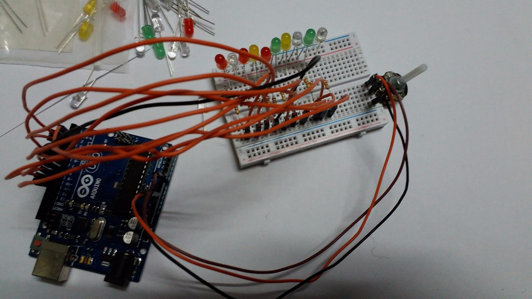
- Bend the cathode of all the 8 LED in such a way that the cathode is inserted in the power rail of the negative supply.Supply the ground pin from arduino to the negative railings
- The annode leg is connected to the digital pin of the Arduino[2,3,4,5,6,7,8,9]through resistor
- now it's time to coding.
Step 4: CODING :-
void setup() {
pinMode(A0, INPUT); // set up the pin for reading the potentiometer // now we have to set up our LED pins as OUTPUTs:
int i; for (i = 0; i < 15; i++) {
pinMode(led_pins[i], OUTPUT); // Default each LED to off. This assumes the anodes of the LEDs are connected // to the output pins (with a 330 ohm resistor in between for current limiting) // and the other side of all of the LEDs (the cathodes) are connected to ground.
digitalWrite(led_pins[i], LOW); }}
void loop() { // we set up a variable to index into our array of pin numbers. We'll default it to 0 (the first // LED) and let its range go from 0 to 14 inclusive (the fifteenth value in our array).
int index = 0; // We'll also need a variable to tell us which direction we are 'bouncing' the LEDs. // We'll start with 1 and use -1 to go the other direction:
int direction = 1; while (1) {
int value = analogRead(A0); // get the position from 0 to 1023 // We'll use this value as the number of milliseconds to delay between advancing to between LED's. // There are 1000 milliseconds in a second so this gives us a good range of delay from 1/1000 to a // little more than 1 second. // But first we need to turn ON the 'current' LED (the one indexed by 'index'):
digitalWrite(led_pins[index], HIGH); // turn the LED pin HIGH, '1', +5v, all the same thing... // Now delay for a time relative to the potentiometer. The 'delay()' function waits the number // of milliseconds we give it before it returns so this works perfect: delay(value); // Turn OFF the current LED before advancing:
digitalWrite(led_pins[index], LOW); // we advance our index number so on the next pass we're talking about the next LED:
index += direction; // We inspect our index to see if we're about to go past either end. If we have reached either // end we will simply multiply the direction by -1 each time we reach one end or the other and this // will toggle it from 1 and -1, getting it ready for the next pass:
if ((index == 0) || (index == 9))
{ direction *= -1; } }
}

![Tim's Mechanical Spider Leg [LU9685-20CU]](https://content.instructables.com/FFB/5R4I/LVKZ6G6R/FFB5R4ILVKZ6G6R.png?auto=webp&crop=1.2%3A1&frame=1&width=306)


