

Introduction: LED and Switch Modules for Prototyping Arduino Projects


Hi! I come back with a tool to help you prototype arduino projects easier!!!
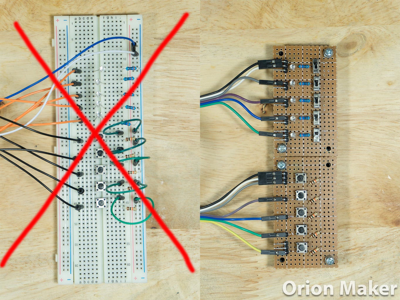
Many DIY Projects contain LED and switch. Building prototype circuit on breadboard costs a lot of space and time, and makes breadboard messy. So I came up with these 2 modules to help you reduce your amount of work on breadboard from LED and switch.
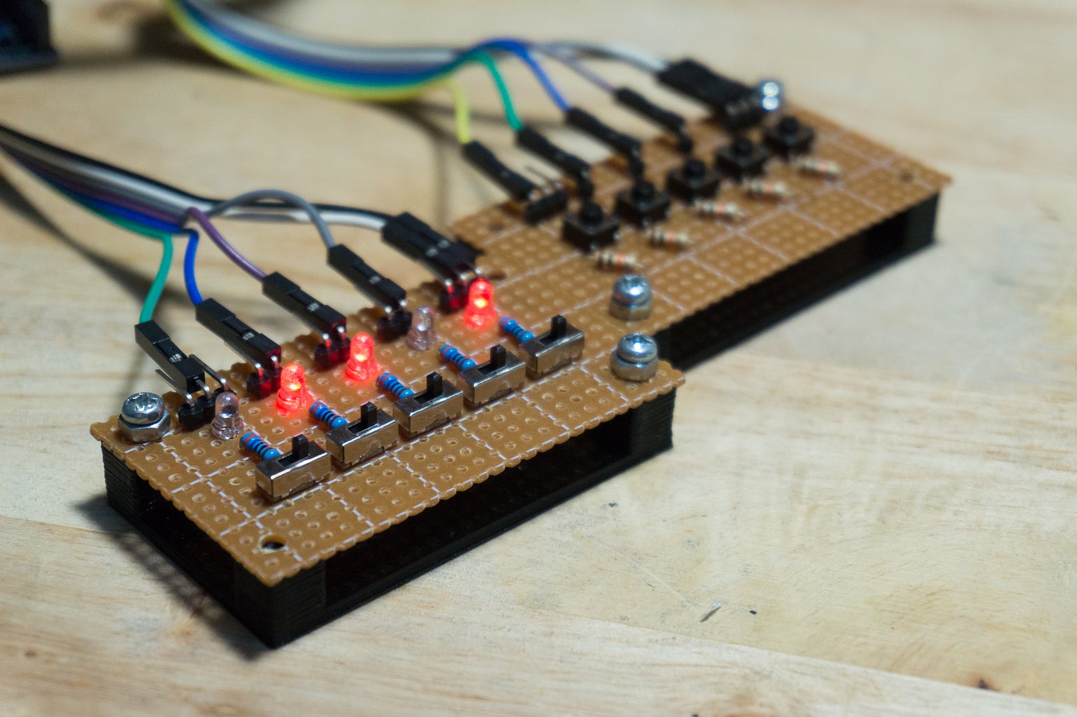
LED module can connect to 5 sources with common ground or individual ground.
Switch module contains 5 push button switch with pull-down resistor.
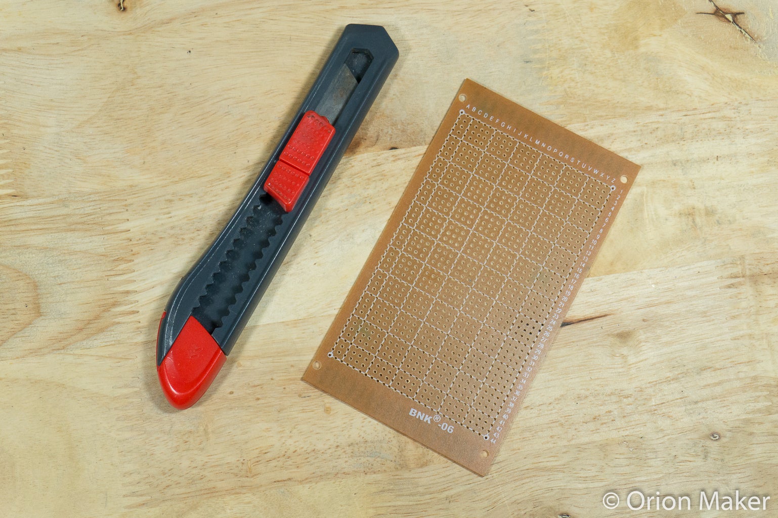
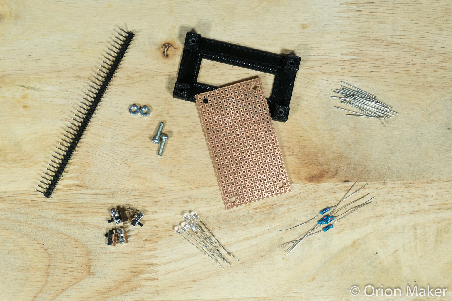
Step 1: Materials and Tools
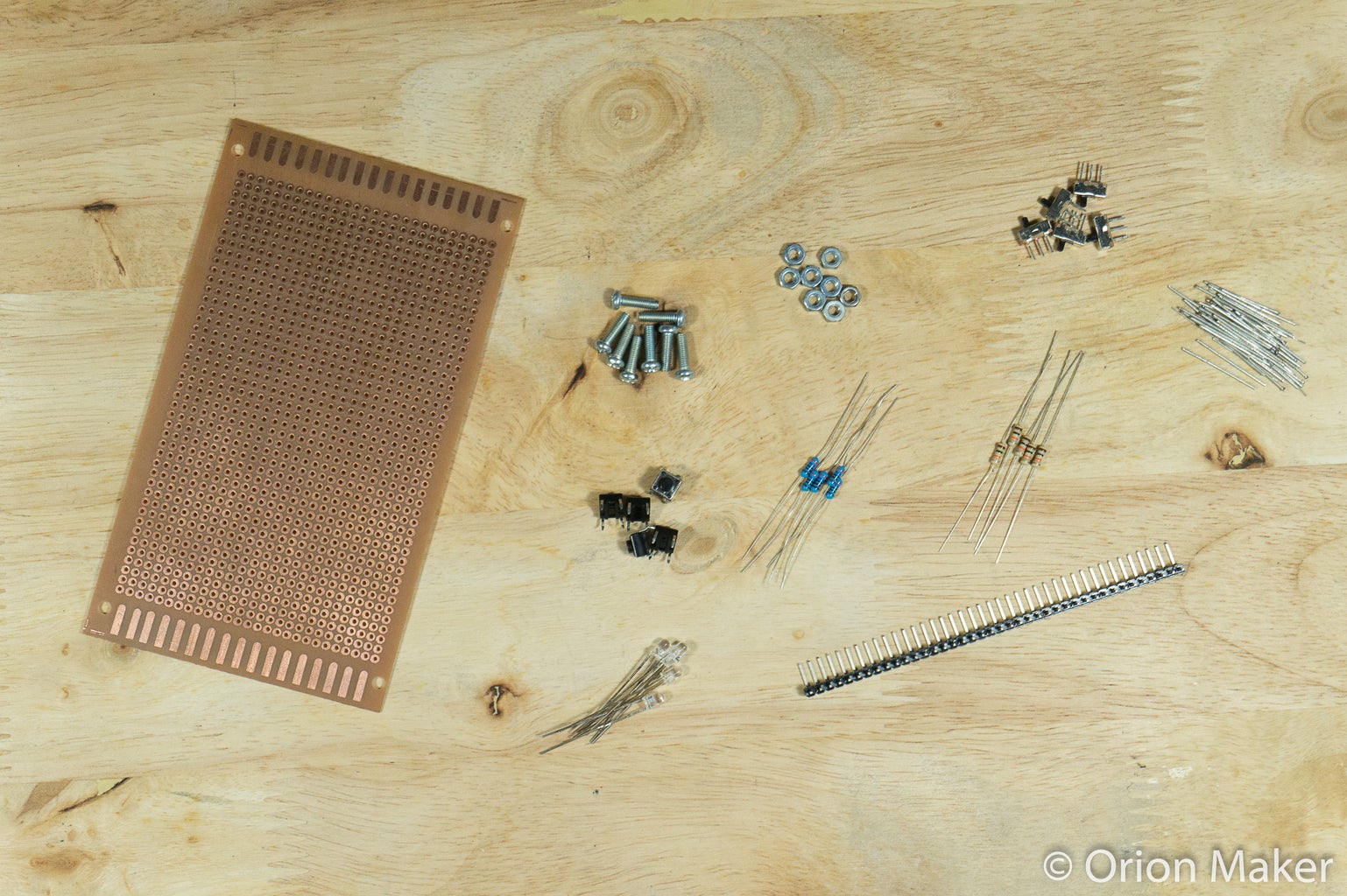

Materials
- Perfboard
- 5x 360 ohm resistors (depend on your leds)
- 5x 10K ohm resistors
- 5x LED (color and size as you want, I used 3 mm red)
- 90 degree Pin Header
- 5x 6x6x5 mm Micro Switch Push Buttons
- 5x SS-12D00G3 SPDT Switchs
- 4x M3 x 10 mm screws
- 4x M3 nuts
- 3D Printed Parts (They are just mounting plates so you can use another things if you don't have 3d printer)
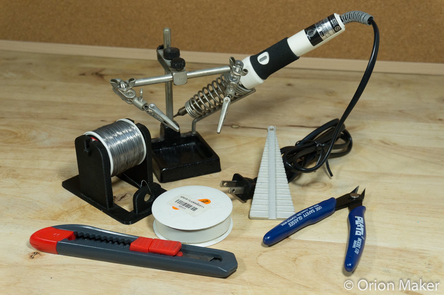
Tools
Basic tools such as screwdrivers, drill, utility knife, etc. Soldering tools
Attachments

Step 2: Prepare Perfboard
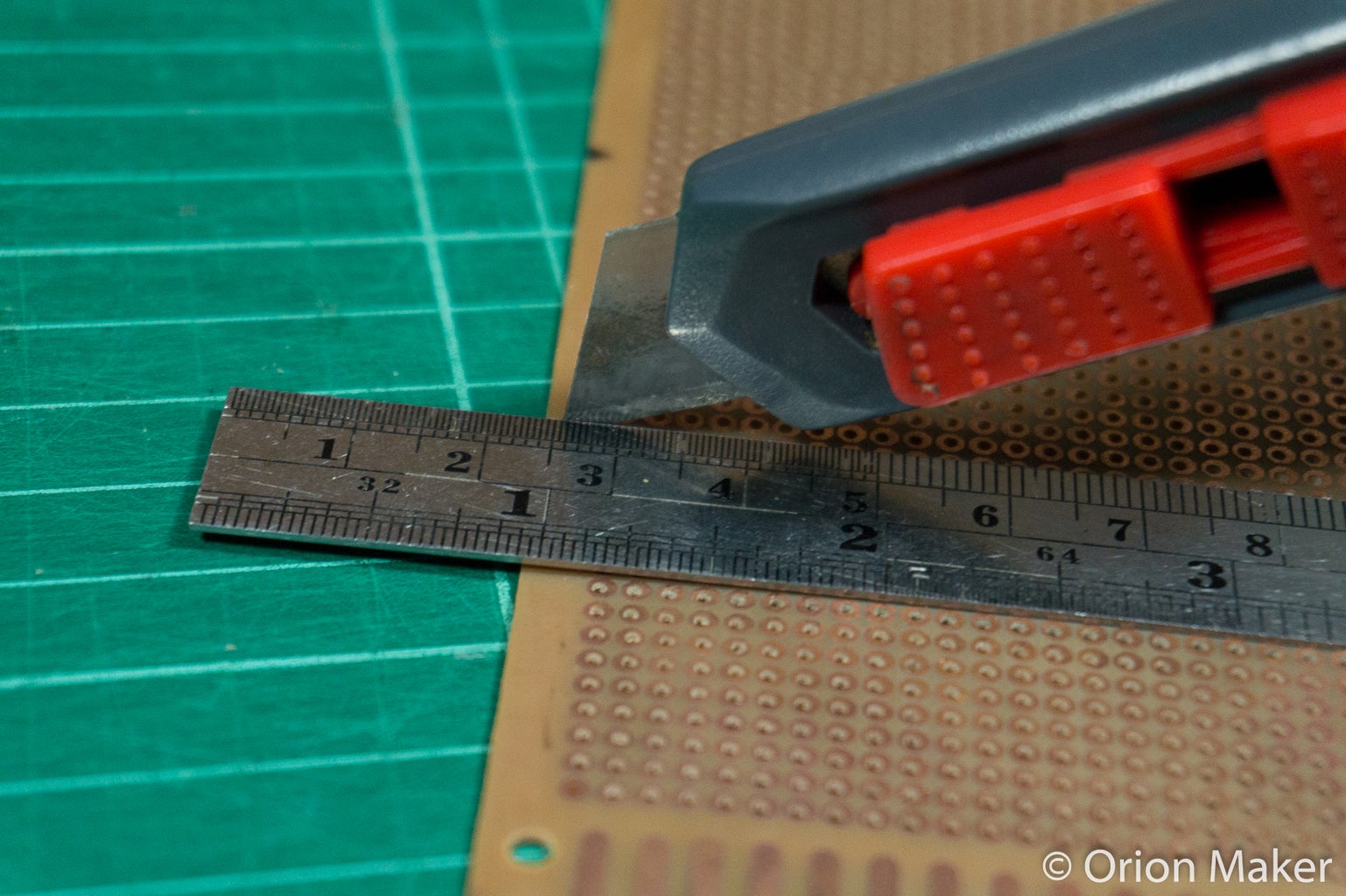
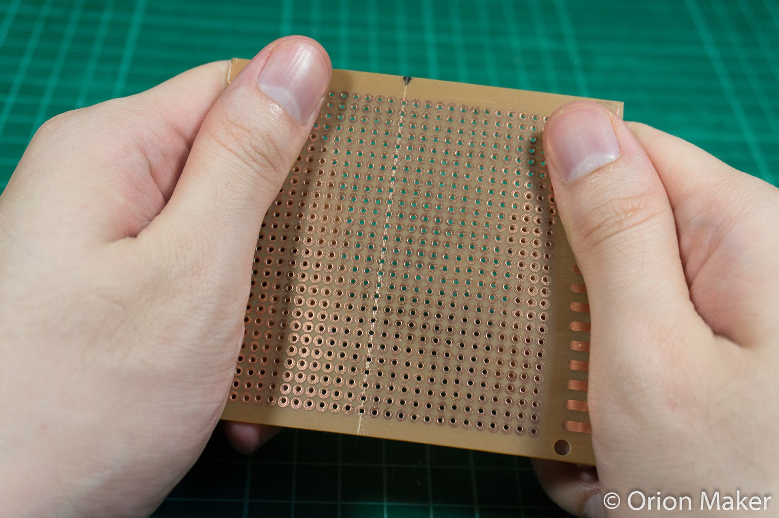
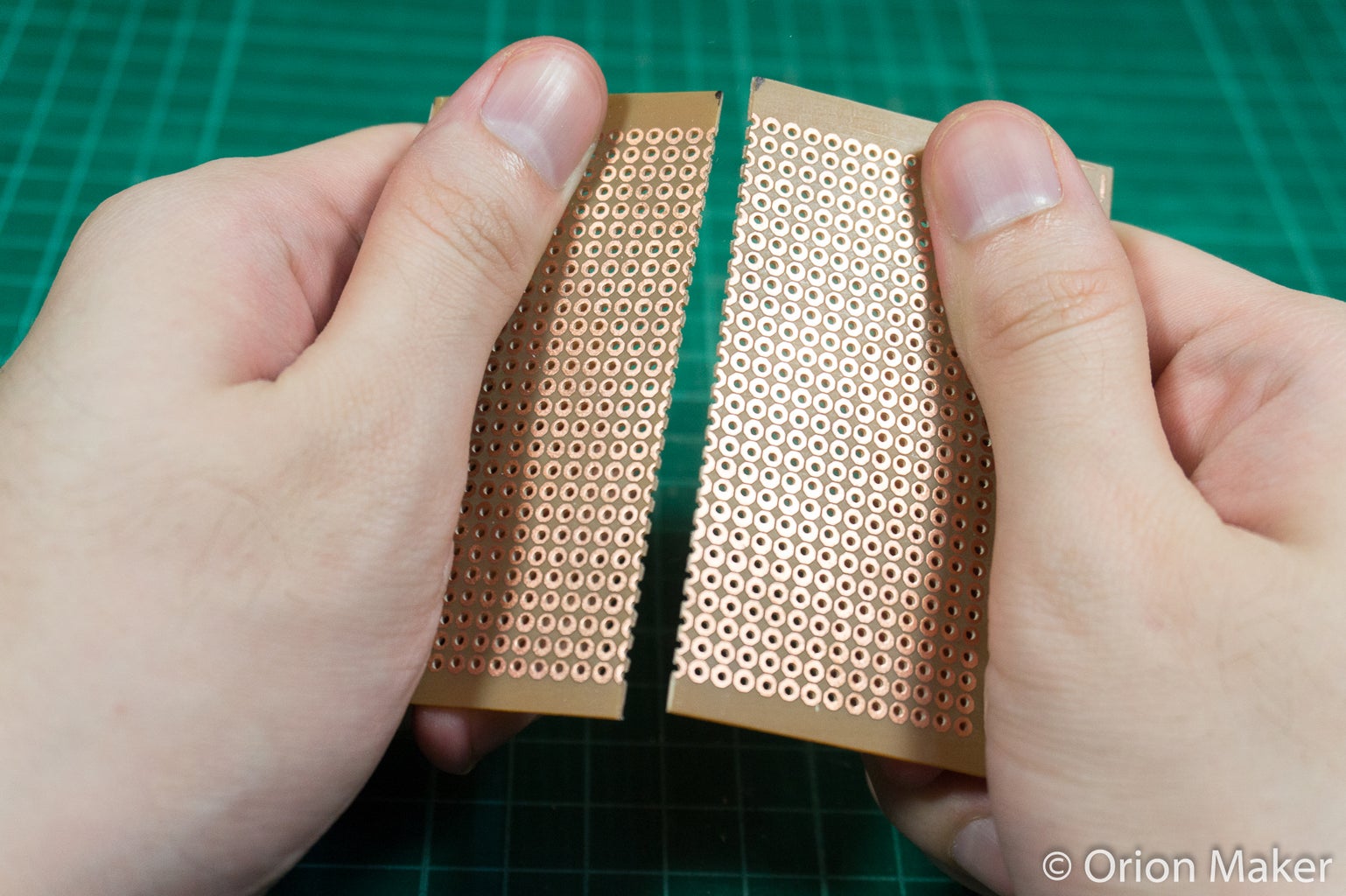
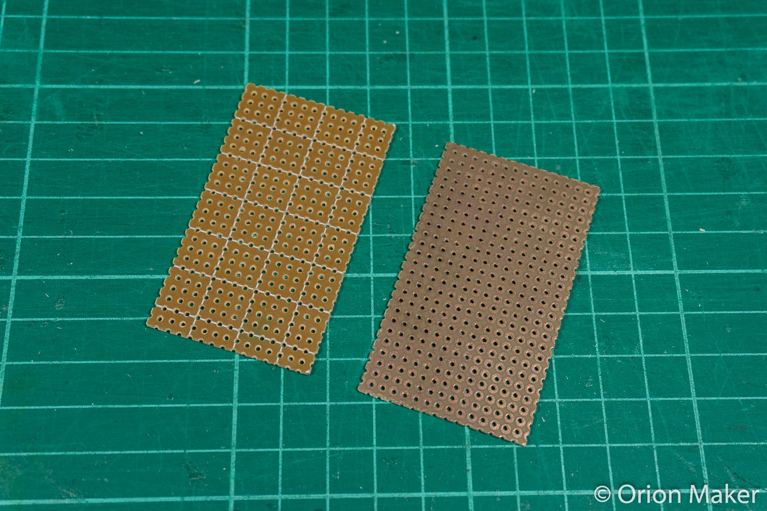

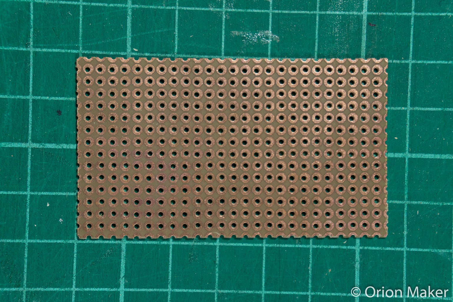


- Cut out 2 pieces of 14*25 dots from perfboard.
- Drill four 7/64" holes on those plates. (see the positions of the holes in the pictures)
TIPS:
An easy way to cut the perfboard is to score both sides with utility knife and snap it.
Step 3: Prepare Components


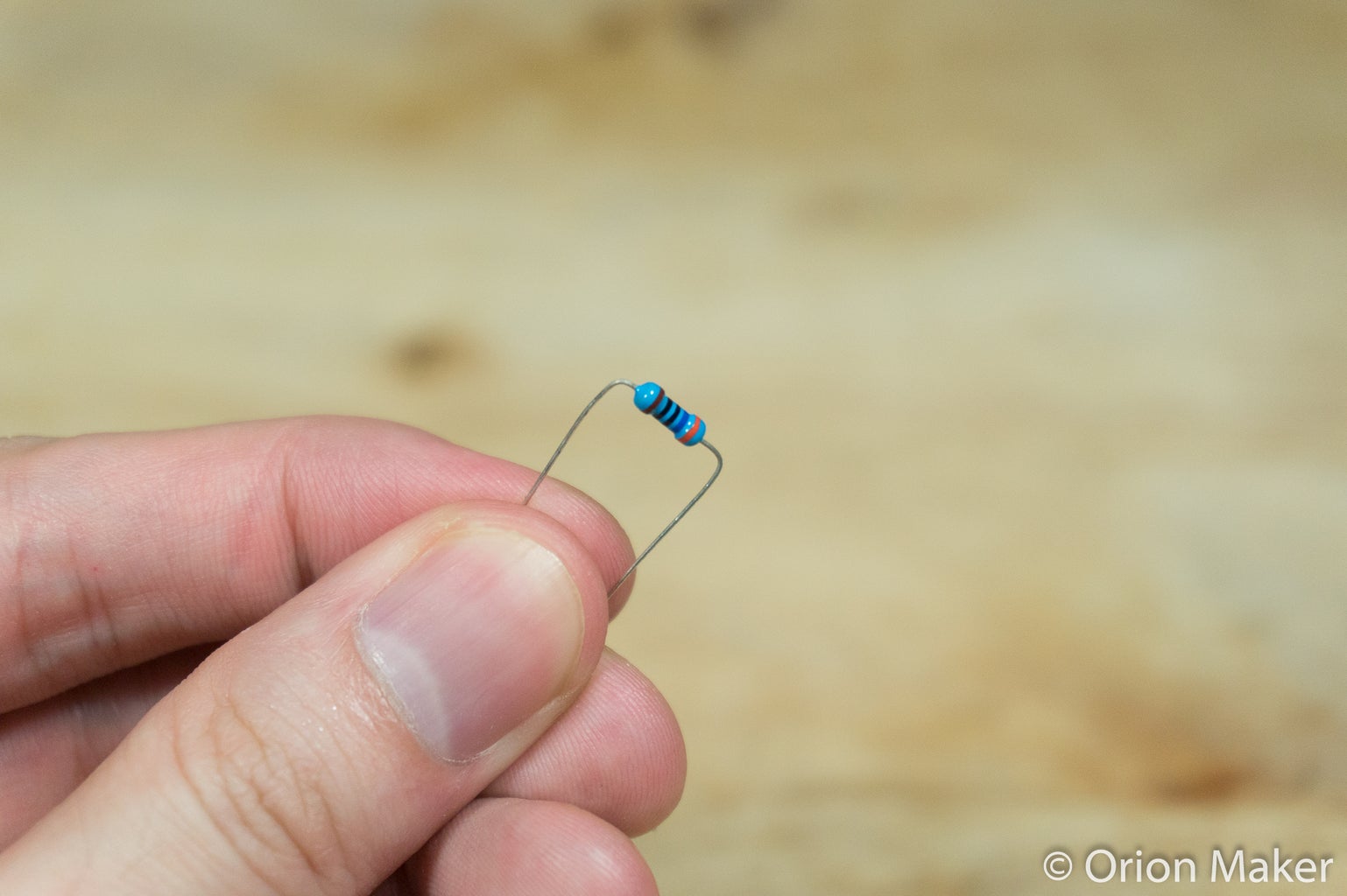
- Cut out
- 2 pieces of 1x3 pin and 3 pieces of 1x2 pin for LED module
- 2 pieces of 1x3 pin and 3 pieces of 1 pin for switch module
- Bend resisters' legs into 90° angles. Resistor lead forming tool is a very helpful tool to help you do this process. You can print it out from thingiverse.
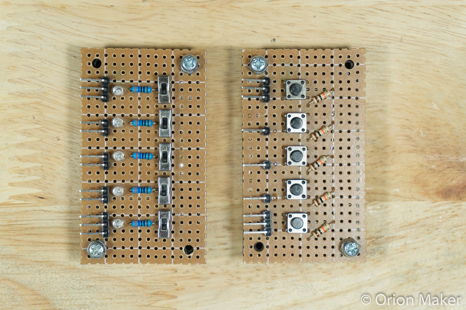
Step 4: LED Module

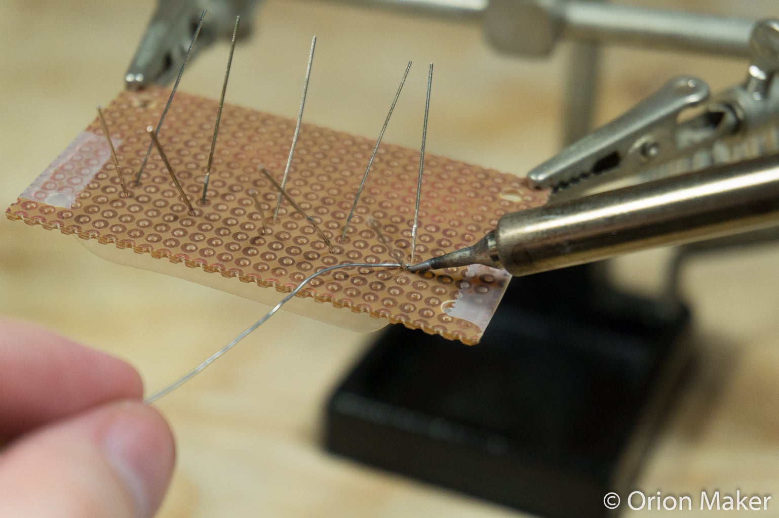
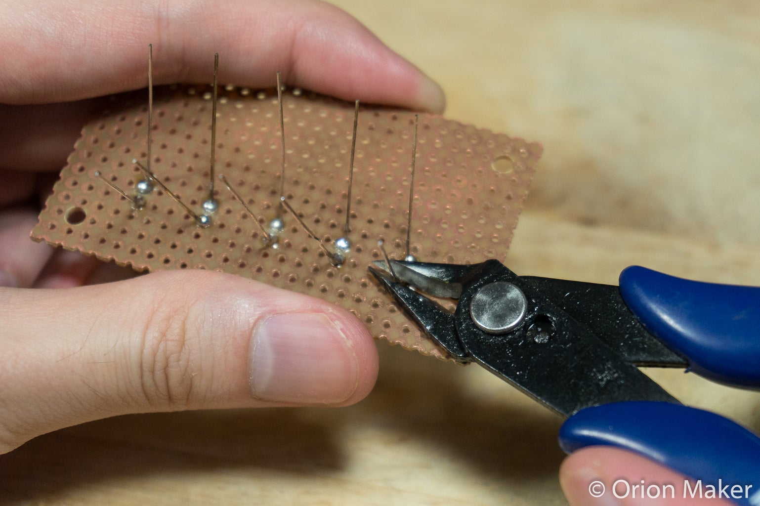


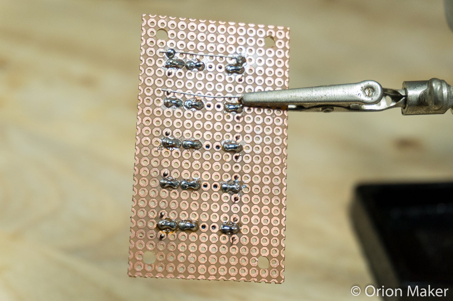
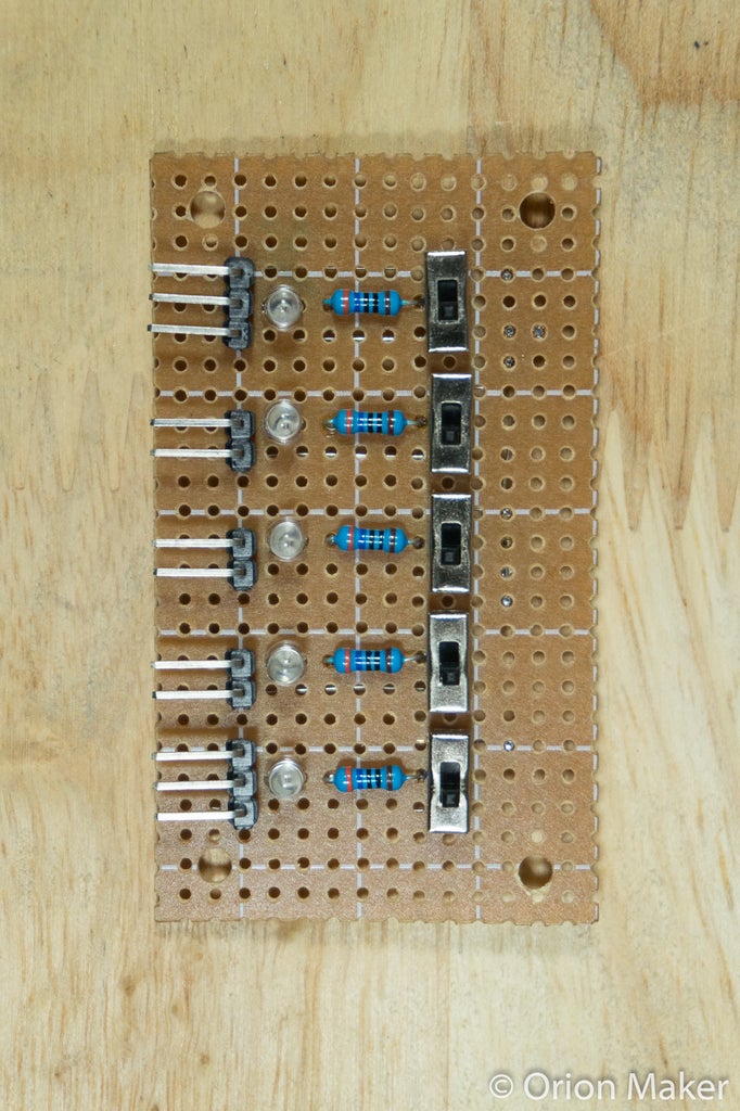
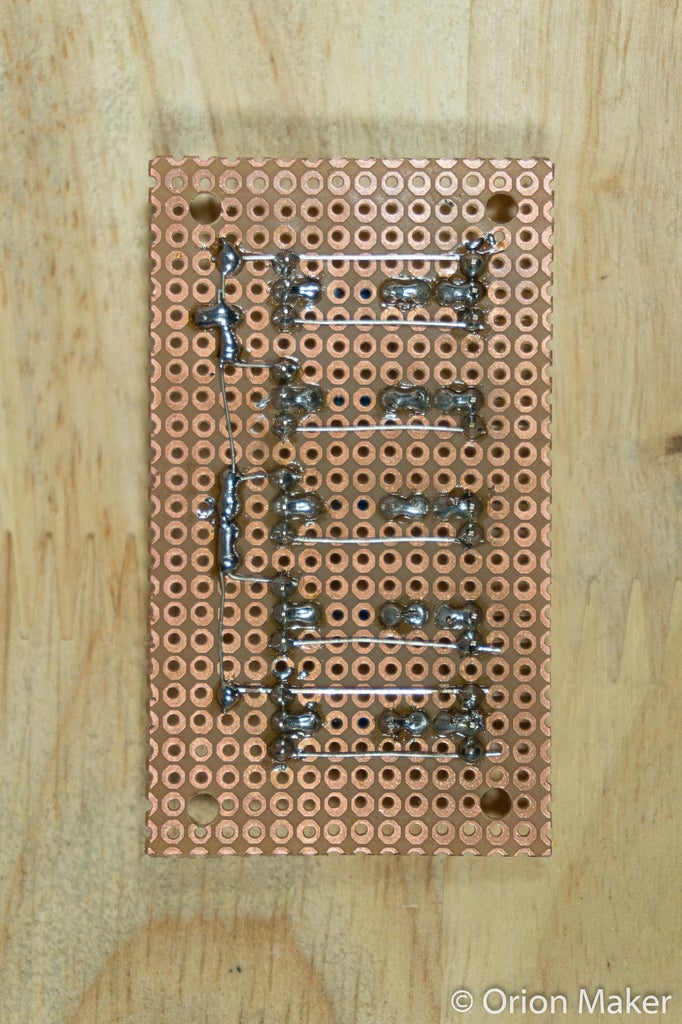
Put and solder all components on the perfboard. (see more details in pictures)
TIPS:
You can use components' legs that you cut out as wires.
NOTES:
The graphic pictures are not exactly 100% accurate, so please also see the actual pictures.

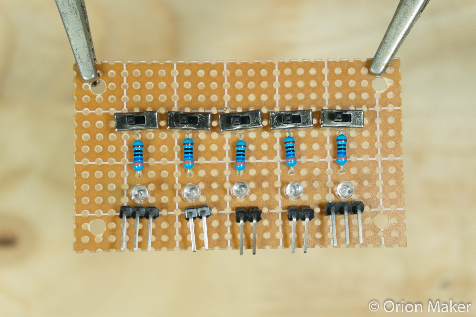
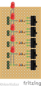
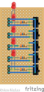
Step 5: Switch Module


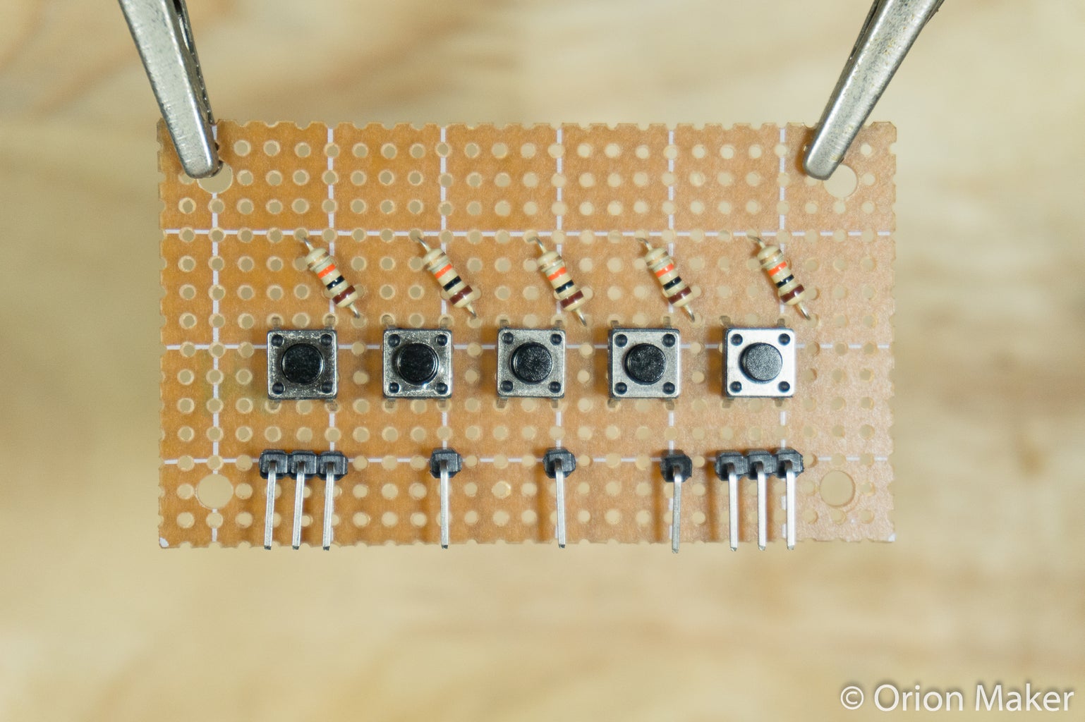


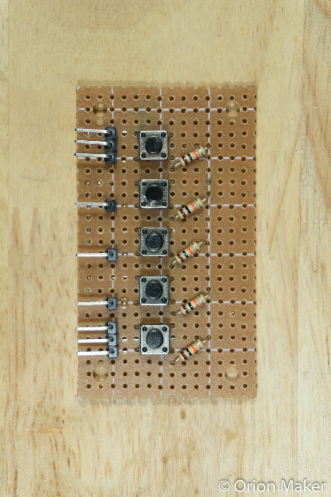

Put and solder all components on the perfboard. (see more details in pictures)
NOTES:
The graphic pictures are not exactly 100% accurate, so please also see the actual pictures.
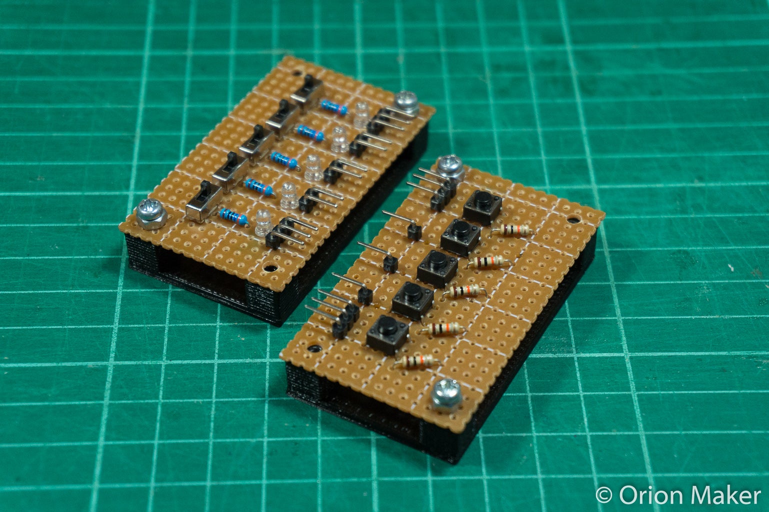
Step 6: Attach to Mounting Plate

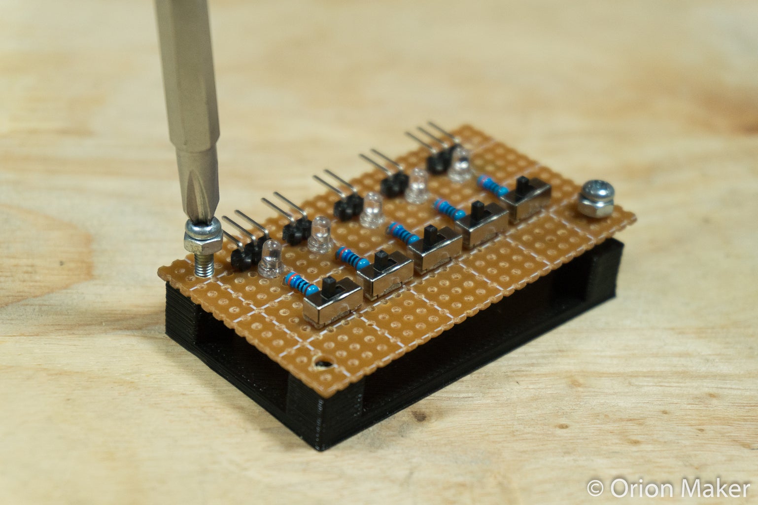
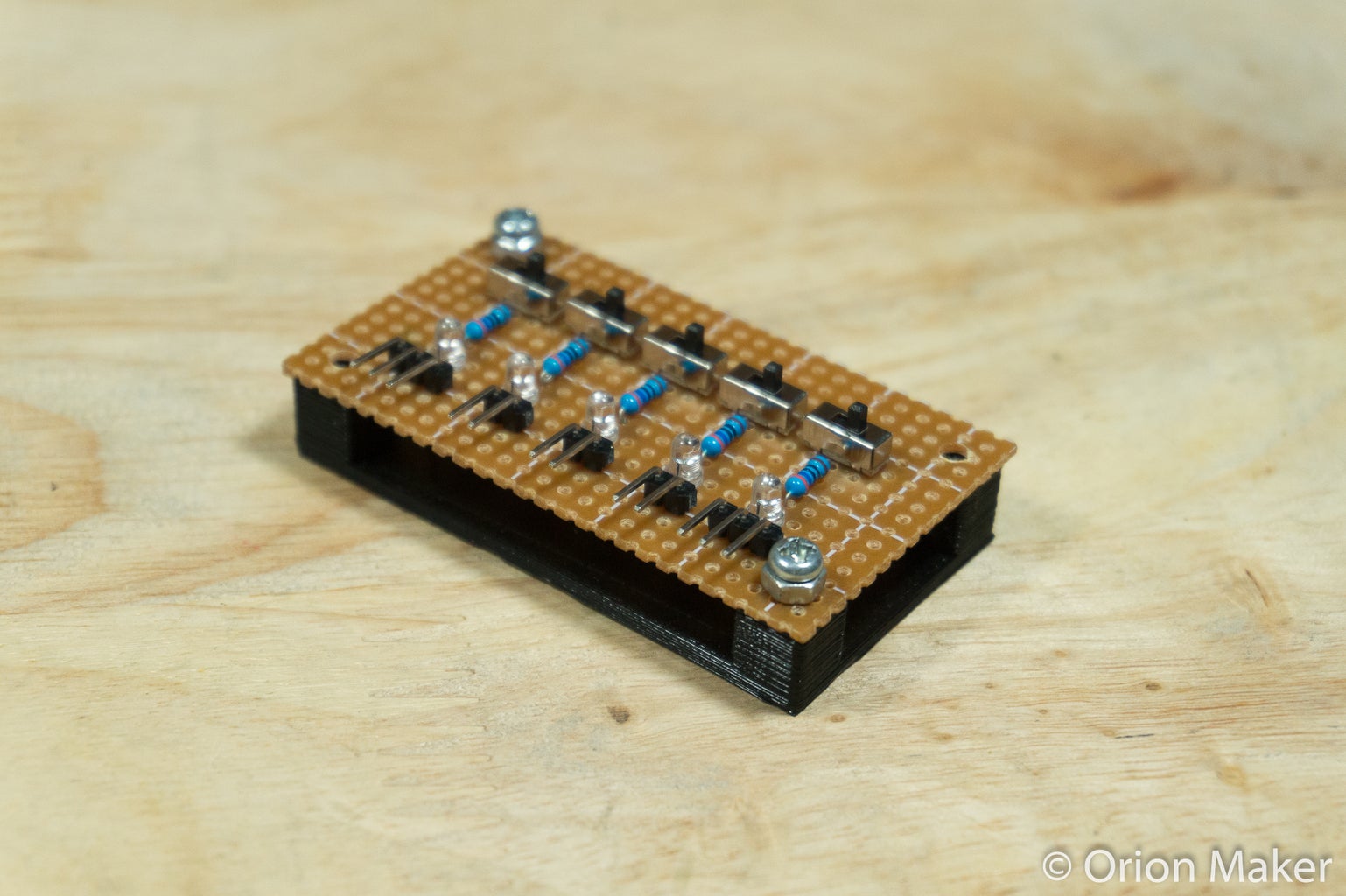
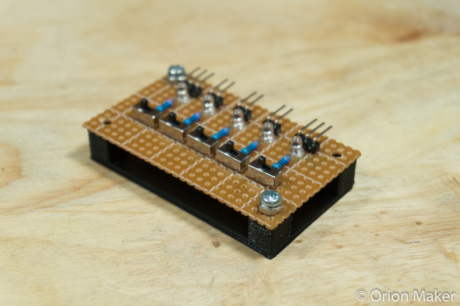

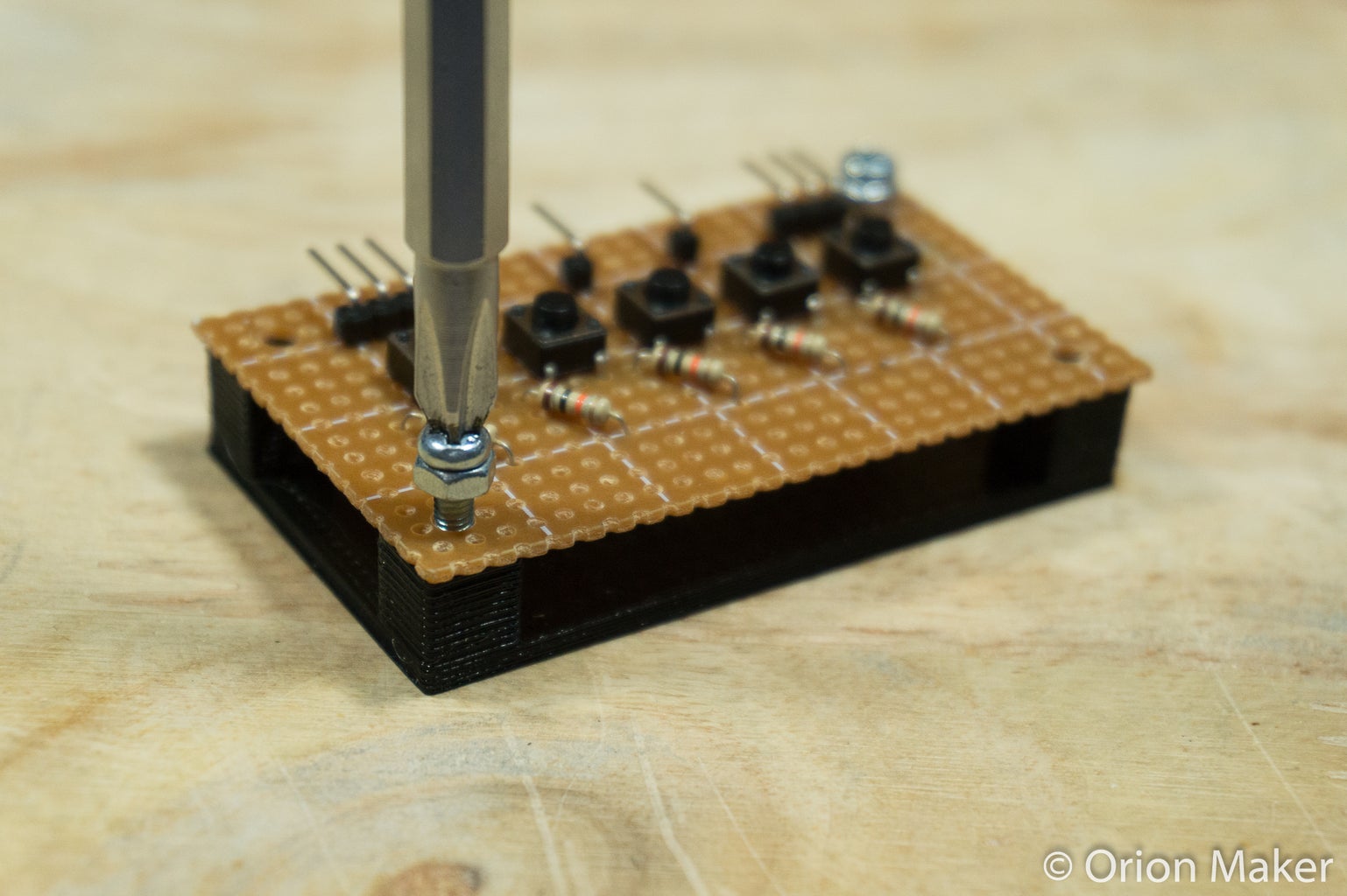
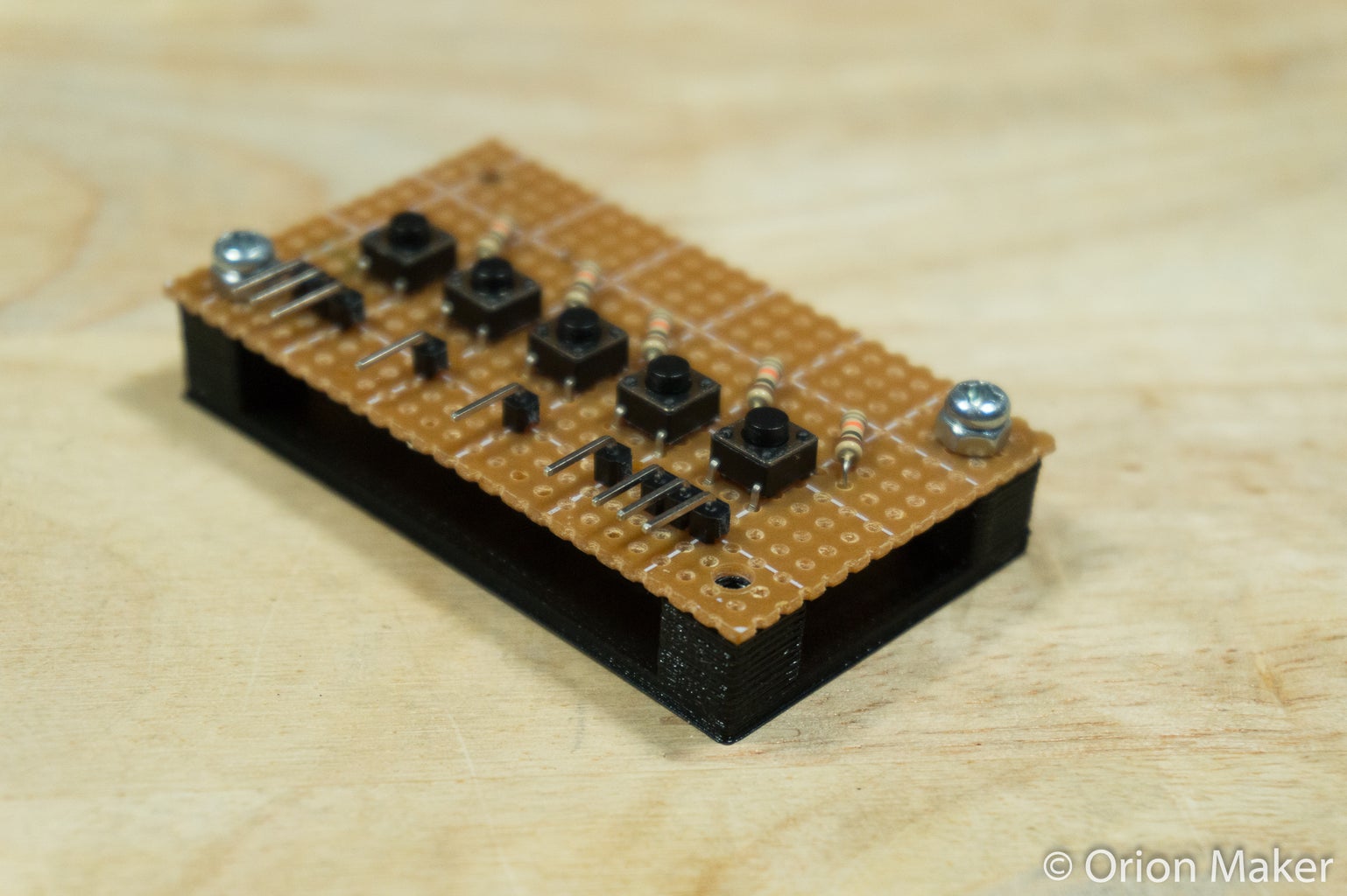
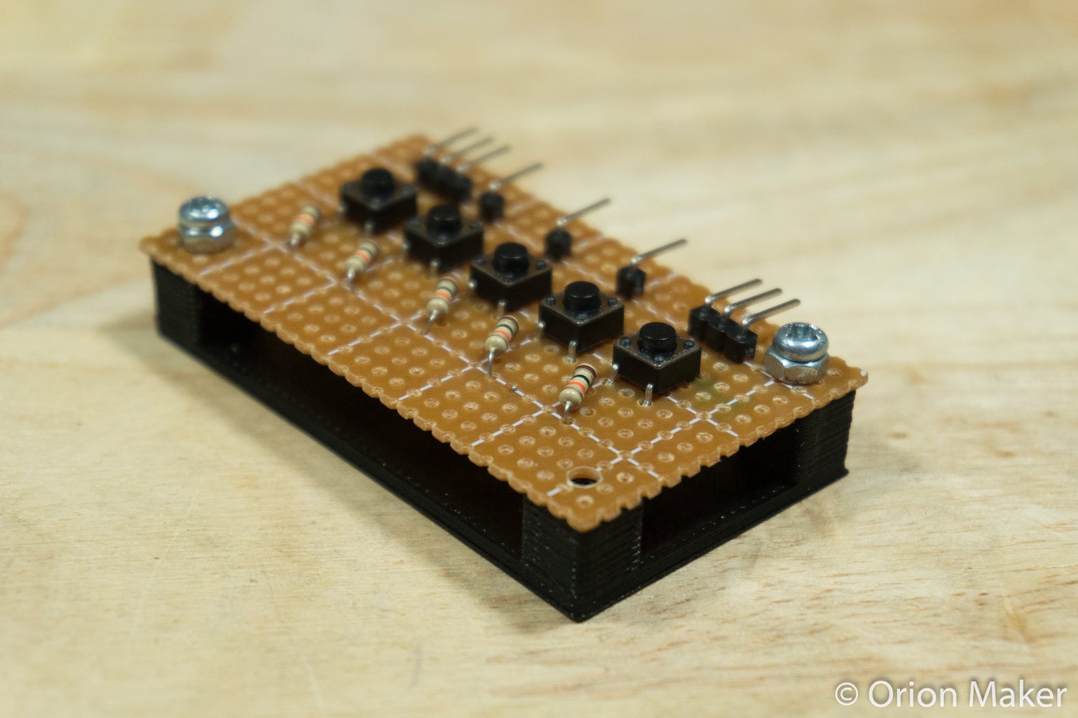
Put the screws through nuts and attach circuit boards to mounting plates. (There is no need for using nuts if your screws are shorter than 8mm.) Use only 2 of them because the position on the circuit boards and mounting plates do not exactly match.
Now it's ready to use!!!
Step 7: One More Things...
- Thank you to my sister who helped me writing these instructions in English.
- Thank you for visiting.
If you like this project, please vote me : ) and don't forget to follow my Youtube Channel and my instructables.
