

Introduction: Laser Centre/edge Finder for a Mill or Drill.


I was inspired to make this laser centre/edge finder after I saw a video on Dan Gelbart's Youtube channel. Unfortunately that video no longer seems to be on his channel, well I can not find it anymore. If you have not seen any of Gelbart's videos I suggest that you search on Youtube for "dan gelbart" but be prepared for a binge viewing session. He has so many additive videos on workshop stuff in general. Most were up loaded six years ago and the newest is four years old.
A laser finder/aligner is an extremely useful add-on for a mill or drill press and can be used for various alignment tasks to a surprising degree of accuracy as Mr. Gelbart had shown in his video. Centering a mill or drill press over a hole or other feature on a work piece is made very easy.
I took his idea and made something to suit my own needs and from materials I had to hand. There were three features that I wanted to incorporate, viz;
1. The ability to continue machining whist it was fitted.
2. Adjustable laser angle.
3. Adjustable focus.
This tool has been made entirely from an old damaged laser level and a few pieces of aluminium from the scrap box, the only "bought" items being two AAA batteries.
The final step links to a video of its use and construction.
Step 1: Preparation of Materials


I cut the end of the old level to extract the laser unit. The laser and its lens were mounted inside a small aluminium housing. I turned this housing to remove the mounting flange which is visible in the photos. I needed to recycle and use this housing because it was threaded internally for the brass lens holder. This thread allows focus adjustment. The last photo also shows the red cap and switch for the battery compartment and a spring battery contact.
The frame was made from some aluminium offcuts from previous projects which were waiting in the scrap box for an opportunity to be useful. The sizing of the pieces is dependent on the size of the machine to which it will be fitted, so that is left to the reader.
Tools needed.
I used a milling machine to shape the frame - most people making this project will be doing it for a milling machine anyway. A bandsaw or hacksaw, files and a drill could substitute for a mill to make the frame if a mill is not available.
A lathe would be useful for making the drill chuck adapter.
A soldering iron to make connections.
Step 2: Construction - Frame


The frame consists of three main pieces. Two form a clamp to mount it to a mill or drill spindle, one of these two is drilled for a battery compartment. The third part is the laser assembly housing which bolts to the battery compartment half clamp such that it can swivel to align the laser to the desired circle diameter.
The two halves of the clamp are united by means of a hinge and bolt. See the first photo above. This design is quick and secure..The hinge comprises of a trunnion made from a piece of 12 mm (1/2") steel bar the length equal to the thickness of the clamp material (in my case this was 19 mm or 3/4"). This trunnion was cross drilled in the centre and tapped for a 6 mm thread. The other clamp had a piece of 6 mm thread fitted which is threaded into the trunnion. The hinged clamp is held closed onto the mill spindle by a single bolt.
Step 3: Construction - Laser Assembly


The original housing for the laser assembly was turned down on the outside and glued to a hole drilled in the new adjustable support piece. The original housing was threaded to suit the brass lens assembly thus allowing variable focus to suit the distance of the laser from the work piece. There is a spring between the lens assembly and the laser which acts as a lock on the focus adjustment.
The backside of the laser assembly was filled with epoxy after small cables were soldered to the laser PCB. These cables went to the battery compartment.
Step 4: Construction - Battery Fitting


The original spirit level had a red screw-on cover for the battery which included an on/off switch. I wanted keep this item but it was screwed in place and I did not have a suitable thread tap. So I cut out the original brass part that it screwed into and glued it into the battery compartment opening. Being brass it was easy to solder a wire to for sending power to the laser. At the other end of the battery hole I fitted the spring contact which is shown in step 1.
Step 5: Balancing


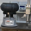
I had made a motorcycle wheel balancing fixture many years ago (maybe the subject of another instructable in the future) which I use for many different balancing jobs. I made up a spindle with a thick disc to fit the laser finder and this enable me to check the balance as illustrated.
I wanted to be able to use the laser device when milling so it had to be reasonably well balanced to avoid creating vibration. Firstly the balance was checked which indicated that there was too much mass concentrated near the laser end. So excess metal was milled away from that area and an adjustable 10 mm steel nut and bolt, as a counter weight, was added to the opposite side. Shown in the second photo above. That brought the balance to an acceptable level.
Step 6: On Mill


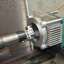
The assembly clamps to the milling machine spindle such that it can rotate with it without obstructing the use of a milling cutter.
As the laser is offset from the axis of the mill spindle the light that it emits will describe a circle on the work piece below. The diameter of this circle is controlled by the distance between the spindle and the work piece as well as the angle of the laser beam which I have made adjustable. Focus can be set, as described in a previous step, to give a visually sharp precise circle.
Step 7: On Drill Press


The utility of this device is increased if it can be fitted to a drill chuck, either in a mill or a drill press. To enable this feature I made a thick disc for the clamp to grab onto with a 12 mm (1/2") centre rod to fit a chuck. The photos show the mounted unit as well as the mounting disc.
Step 8: Problems


When I first started testing the laser device in my milling machine I observed what seemed to be a strange phenomenon.
Initial hand rotated tests gave perfect results, however once it was rotated mechanically it would reach an RPM when some of the circle would disappear. Weird yes? Anyone guess the problem? At speed the batteries would centrifuge away from one of the contacts, I forget why it didn't turn off for a whole revolution, but there was a logical explanation. The fix was simple, I just used a stronger spring in the battery compartment.
Step 9: A Modification


I have to confess to making a stupid mistake with the initial construction of the clamp.
I made it to have four contact points with the mill spindle. With four contact points there will be one that is either not touching or not touching as hard as the other three. In practice this did not create any problems, the clamping was always secure. However, the purist in me would not rest until I modified the clamp to a three point contact.
This first photo shows how I first fixed it in photoshop and anyone planning on making their own version is advised to make something along the lines of the photoshopped clamp.
I fixed it physically by cutting away the area of the original two contact points and then I fitted a flat head screw to provide the single contact on this half of the clamp giving a total of three clamping points.
Step 10: Usage and Summary


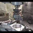
These photos show one job for which the laser centre finder was a huge time saver.
I needed to counter bore the cover mounting screw holes in a motorcycle crankcase to enable the fitment of small "O"-rings to seal oil. Did I mention that I have always hated paper gaskets?
The first photo shows how I could centre over each hole. Once centred I only needed to plunge the mill quill down to the set cutting depth and move on to the next hole. The whole operation was performed very quickly.
I have created a very useful tool from items that would otherwise be considered as 'end of life' junk. The construction time was only a few hours and I have achieved the three goals outlined in the intro. which I duplicate here for completeness.
1. The ability to continue machining whist it was fitted.
2. Adjustable laser angle.
3. Adjustable focus.
I have shown the only problem that I experienced to aid anyone who might experience the same and I have also outlined a stupid mistake so that can be avoided by others. In the real world the mistake did not cause a problem but was not theoretically correct.
If you found this presentation interesting and/or useful please like, share and subscribe.
I intend to enter this into the "Trash to Treasure" contest so please vote for it. Thanks for watching.
Step 11: And Now the Movie

Participated in the
Trash to Treasure


