

Introduction: Laser Pointer Switch


This instructable will detail how to make a switch that uses an arduino to sample light. When the light sample reaches a threshold it will trigger a relay that can be used to turn on/off a small appliance (light, radio, fan, etc...) The parts for this instructable can be ordered as a kit:
Jameco Kit
http://www.jameco.com/webapp/wcs/stores/servlet/Product_10001_10001_2209967_-1
Step 1: Review Relay and Prep Wire
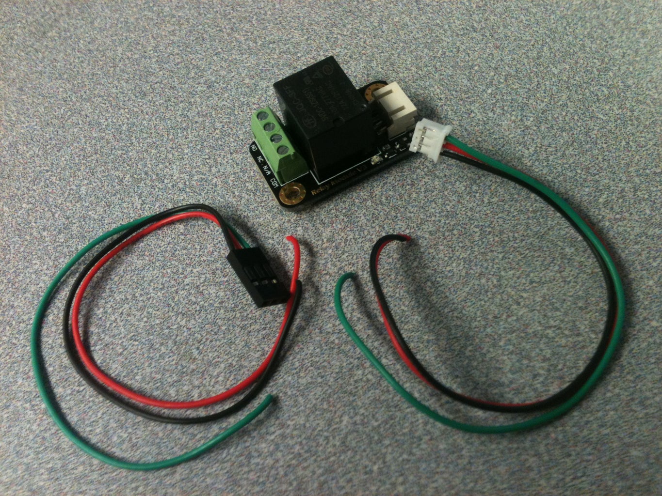
unpackage the relay and stretch out the cable. this cable is used to activate the relay but will also be used to power the arduino. cut the wire in about two equal parts. the part with the white clip end will plug into the relay and be soldered into the arduino. the wire with the black clip end will be spliced into the usb cable to supply power to the arduino. this is also a good time to review the relay tutorial for safety information: http://www.dfrobot.com/wiki/index.php?title=Tutorial:_DFR0017_V2_Relay
Step 2: Modify USB Cable
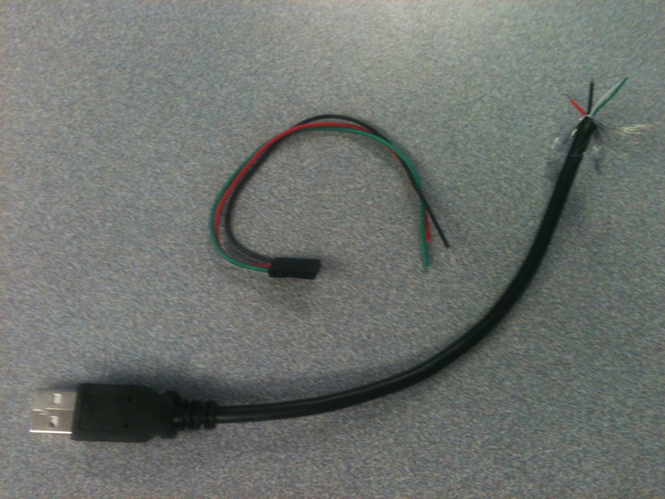
cut the USB cable about 6 inches from the end with the rectangle end. strip the wires and you will find a red, black, green and white wire. splice the red and black wires from the relay cable (with the black end) to the red and black wires of the USB cable. solder the connections and tape the wires. this new USB cable will be used to power the arduino.
Step 3: Identify Arduino

find the arduino in the kit of parts and familiarize yourself with the pin holes and orientation of the package.
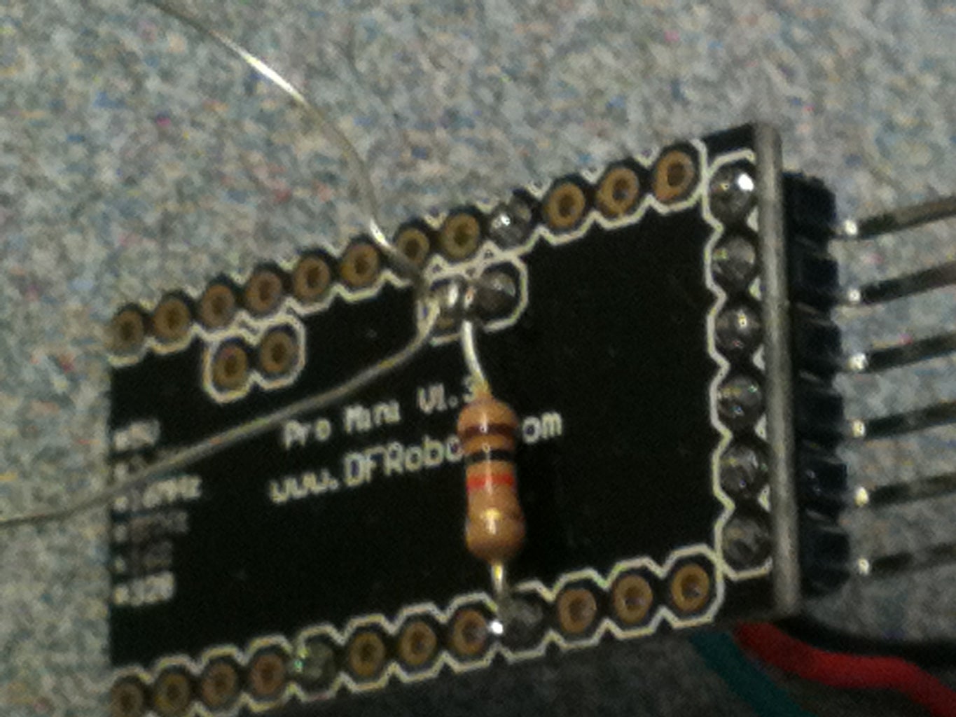
Step 4: Component Layout

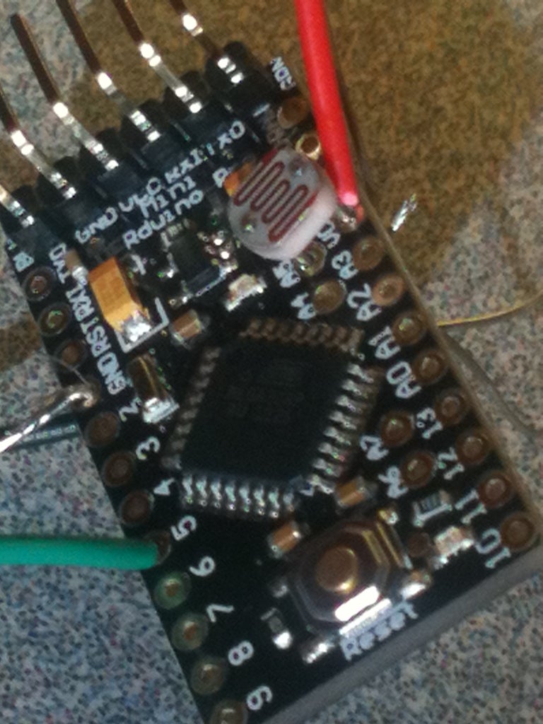
the components that are soldered onto the arduino need to be placed in specific places. the right angle header goes into the right side of the arduino. the photo cell needs to have one leg in the A5 hole and one leg int the Vcc hole. the resister needs to have one leg in the GND hole and one leg in the A5 hole (with the photo cell) . the wire from the relay (with the white end) needs to be soldered into the arduino also. the green wire in the 5 hole, the black wire in the GND hole (with one leg of the resistor) and the red wire in the Vcc hole with one leg of the photo cell). on some arduinos, the resistor leg and the photo cell leg will not fit in the same hole. if this happens to you, you can put the resistor in from the back of the arduino and connect the photo cell leg to the resistor leg behind the arduino.
Step 5: Solder Arduino
for the holes that have a wire and a component leg in the same hole, make sure to put the wire in the hole first then push the component leg in. after all the components are in the proper place, solder them.
Step 6: Program Arduino

connect your arduino to the FTDI device that you use to program it then upload this code to your arduino:
//adjust the lTrigger number for your light values
int lTrigger = 610;
int photoPin = A5; //define a pin for Photo cell
int ledPin=5; //define a pin for relay activator
boolean bLatch = false;
int lLaser = 0;
void setup() {
Serial.begin(9600); //Begin serial communcation
pinMode( photoPin, INPUT );
pinMode( ledPin, OUTPUT );
}
void loop() {
lLaser = analogRead(photoPin);
if (lLaser > lTrigger) {
bLatch = !bLatch;
digitalWrite(ledPin,bLatch);
delay(1000);
}
Serial.println(lLaser); //display photocell value to serial monitor.
delay(10); //short delay for switch bounce
}
test your arduino with the serial monitor open to see the light reading values. adjust the trigger value to a range that works best with your laser pointer
Step 7: Prepare Power Cord

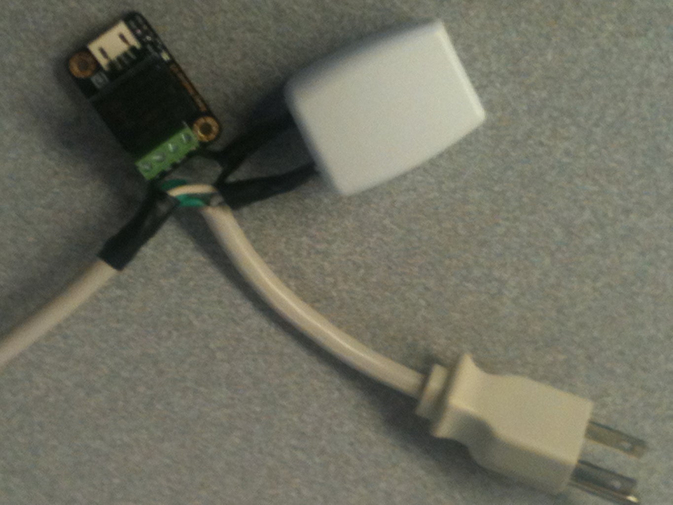
the power cord is the short extention cord that we will use to power the arduino (with USB block) and the appliance that is switched (with the relay). this cord will be plugged into a power outlet and the electrical properties can be hazardous. please be careful when working with this cord and the relay when it is powered. you will want to cut the power cord a little off of center. to complete the wiring of the relay we will need a short piece (1.5 in) of the black wire. cutting the whole wire a little off center will allow us to cut a piece from the black wire to complete the connection.
using the end of the power cord that plugs into the wall, connect the black wire and the short black piece to one leg of the USB block. connect the white wires from both ends of the power cord to the other leg of the USB block. connect the green wires together so they dont touch any part of the USB block. connect the short black wire to the COM header on the relay. connect the black wire from the other power cord end (the end that your appliance will be plugged into) into the NO header on the relay. tape any bare wires and the USB block ends to avoid accidental contact with wires and you.
Step 8: Connect Parts
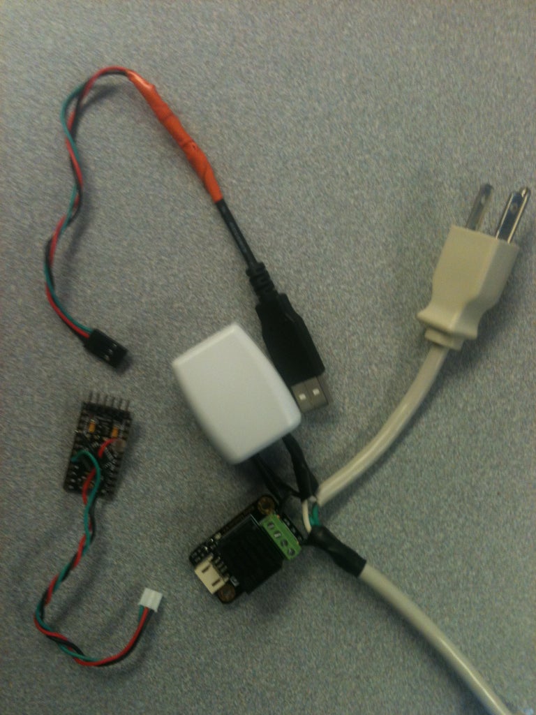

plug the USB wire into the USB block. plug the other end of the USB wire into the arduino header pins so the red wire is on the Vcc pin and the black wire is on the GND pin. the green wire will end up on one of the pins but will not connect since we didnt connect the green wire to any of the USB wires. plug the relay wires from the arduino into the relay. arrange the components so they can bundle into the enclosure.
Step 9: Install in Enclosure

orient the bundle so the power cords can come out of the enclosure and the photo cell can be seen through the enclosure. you will need to cut a channel in the side of the enclosure for the power cord wires. after cutting the channel, put the bundle in the enclosure and secure the top on the enclosure.

Participated in the
Sensors Contest

Participated in the
Lamps and Lighting

Participated in the
Gadget Hacking and Accessories Contest


