

Introduction: Fail Safe for the Arduino Bluetooth Module Using an EC1 Splat PLC


The EC1 Splat board available at Splatco.com is a EOM embedded controller that is capable of multitasking upt to 64 processes at once, some features include PWM (pulse width modulator) outputs, floating point and much more including interfacing with the JY-MCU Bluetooth Wireless Serial Port Module. A problem recently encountered was that the EC1 and the BT module do not have a programming command for when the BT module gets disconnected from the android device. in this instructable I will show you a simple and easy way to fix this with only three lines of programming (not including the Bluetooth hash functions)
You will need:
Basic soldering skills and equiptment
The EC1 board available at Splat
The JY-MCU Bluetooth Wireless Serial Port Module and its connection cable (comes with it)
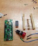
A single wire about six inches long with a female pin connector on one end (see picture)
A standard micro USB to USB cable
A computer running SPLat/PC, the free SPLat programming environment (IDE)
small wire cutters for removing shrink tubing
Now lets get started!
Step 1: Uncovering the BT Module
The first thing we need to do is remove the shrink tubing from over top the red LED in the corner of the board
Using some small wire cutters carefully cut a slice out of the corner until the entire led is accessible.
Step 2: Solder the Wire

Using the soldering iron you can now strip and solder the wire to the positive end of the led, this should be the end nearest the four prong plug. There are two solder pads already there, the one closest to the edge is directly connected to the LED, this will make soldering a bit easier.
Step 3: Plug in the Module

Plug the BT module into the Splat EC1 with the provided cable *note that the pinout on the BT module and the EC1 are not in the same order, I would recommend placing the plugs in their correct spot then glue them together with a dab of hot glue.
Then plug in the wire we just soldered to whatever input on the EC1 you would like to use, however the input must be 5v tolerant
you can find a copy of the EC1 pin out on the Splat easysteps
For this demonstration i will just use input 2 on pin 21 of the EC1
Step 4: The Program

Next is were it gets tricky, if you dont have any past Splat programming experience you will need some but not too much, also since the BT module uses SimpleHMI you do not need to program anything on the android phone. For this I will use the "A first sample app using Bluetooth to android"
The program looks like the image above
Step 5: Add What We Need to the Program

Now we will add some lines of program
First directly under the seccond gosub command we will type:
pause 20
off 1
launchtask monitorconnect
Then at the bottom of the program on its own line we will type the following
monitorconnect
waiton 2
on 1
killtask
The program will now look like the picture above *the stars mark changes*
*Also the program is cut off at the top in the screenshot*
Step 6: Testing
By this point you should be able to load the program on the splat board and test it, the demo program will flash the red light when you touch the button, the program we just wrote will turn on the red led when signal is lost and turn it off when signal is regained. This part of the program can be rewritten for any purpose. Thank you for following along in this indestructable! If you need any more Splat gear you can find it on www.splatco.com


