

Introduction: NES Inspired Simple Phone Stand.


I saw the instructable to make a simple phone stand from a cassette case by "cgingerich", and I thought that it needed some actitud. So I modded it to have a NES controller appearance, to fit my Nokia C6, and to use it as a kind of a dock. And this is how it turns out. Hope you like, and add it your personal touch.
By the way, this is my second instructable, so please be patience with me. And sorry for my bad english. Once again, thanks
Step 1: Materials

For this project, I used several things I had around, left from other projects. I LOVE TO RECYCLE.
But what you really, really need is:
- 2 or more cassette cases
- Electrical tape (any kind of tape will do, but I kind of like working with duck tape and electrical tape)
- Paint (I used black and grey spray paint)
- Some pieces of sand paper
- Super glue, and hot glue
Also you could use:
- Some very soft fabric (to put inside the stand to prevent scratches)
- Adhesive printable paper
- Plastic pieces
And you could also use:
- 16 gauge cable of diferent colors
- An old cellphone battery
- An AAA rechargeable battery
- An old cellphone desktop charger
- 3 small switches
- An usb B, and an usb A connector
- Leds of diferent colors
- And finally a connector that fits into your cellphone
- And a male and female connector (I used 2.5mm kind of headphone connector, I used a smaller one so nobody could try plug their headphones into the charger)
Step 2: Tools

This is the list of tools I used:
- "Moto-tool" (Dremel)
- Hand saw blade
- Vernier Caliper (you could use a ruler, if you are careful)
- Knife
- Diferent sizes files
If you want to do the charging part, you will also need:
- Soldering iron
- Cable peeler
Step 3: Cutting the Cases

The first step is to mesure the lenght of your cellphone, divide it in half, and mark the cases.
Make sure you leave some extra room, so you will have an margin error. Also make sure from were are you mesuring, otherwise you will end up with a shorter stand, and you will have to start over.
After you make the marks, re-mesure it. There is an old saing that says: mesure twice, cut once.
When you are 100% certain you make the right marks, cut it with the motortool.
Step 4: Try It Up


After you make the cut, use a file to remove the left over plastic, and make a clean straight cut.
Then you could paste the two halfs together with the tape, to try it out.
Step 5: Extra Cuts


When I try it out, I notice I had to make some extra cuts. One was in the front of the stand, so it dosent cover the phone keyboard. Another one was in the back cover, so the phone will stand in a nicer angle, you will see what I mean in the photos.
Step 6: Polish


After you had test it, and you are happy with the result, it time to polish it a bit.
First I remove the tape from one side, put some super glue in between the parts, and waited until it is dry.
You will want to use some sandpaper to smooth the surface, and make it ready to paint it over.
Clean up the sandpaper dust, and put a new piece of tape, and you wii be ready to paint.
Here you could make a stop, and leave it with just the painting.
Or you could continue to see the rest.
After the paint is dry, super glue the soft fabric inside the stand, and cut the excess fabric with a knife. Use a ruler to push the fabric and make sure it fits in all the corners.
Step 7: Setting Up Charging System


For setting up the internal charging system, you will need to print out a test image, so you could have an idea were to put every component. In this step I notice that I needed to lower the start and select buttons, so the leds that I was planing to use were centered.
After you make this, you came make the holes to fit the switches and conectors. I used an small prismatic file to make the holes for the switches.
I also used the hand saw blade to cut as low as I could the pastic pieces that hold the cassette reel, and then sand it to have a flat surface.
Step 8: Charging Schematics


Sorry about the schematics, but I had to do them in paint, still they are very simple.
R = 180 ohms for an 1.7V LED
First you have the USB B in, there it goes to 2 doble switches that you activated at the same time.
So you have 2 opctions:
- The first is to ligth up a LED and connect to the USB A out. Where you could connect you cellphones usb cable or blutooth dongle.
- In the other option, it connects to another doble switch, were you can select to charge the cellphone battery, or when not in use *, the internal battery. The other opction of this switch is to select the internal battery to charge the cellphone.
*When you connect the cellphone cable, it disconnect the internal charger. For this I use the female 2.5mm connector.
In case your phone needed more than 3.7V to charge, you could put in series an "AAA" battery, to raise the voltaje around 5V. This is the simplest way to get 5V I could think of. Some people like to use an DC-DC riser, but this increases the consuption, and you dont have that much space left.
After you make all the connections, you can use hot glue to put all the components in place.
Step 9: Testing the Connections, and Setting Up for the Final Touches


Before you plug this to your computer or cellphone, make an small connection test. Make sure there isint any shortcircuits, and that you made the right connections everywhere. You dont want to burn your phone or computer.
Then test the internal battery charger, pluging it to the computer or an USB charger.
If everything is in order, you are ready to continue.
Use a Qtip with acohol to unpaint were the leds are, so they can be seen from the outside. If needed, use a knife to take a piece of the tape.
Step 10: Buttons


To make the buttons, I grab the covers from two plastic jars, one red and one gray. I cut the top of both covers, and save the rest for another project. From the top I cut off some pieces, larger than the final buttons, and paste two of the pieces together. When the glue has set, I used the Moto-Tool and a grinder piece to give it the final shape. If you, like me, isint that great using the Moto-Tool, I sugest you use a paper mold, and when you are close to finish, pass from the Motor-Tool to sand paper, to give it the final touches.
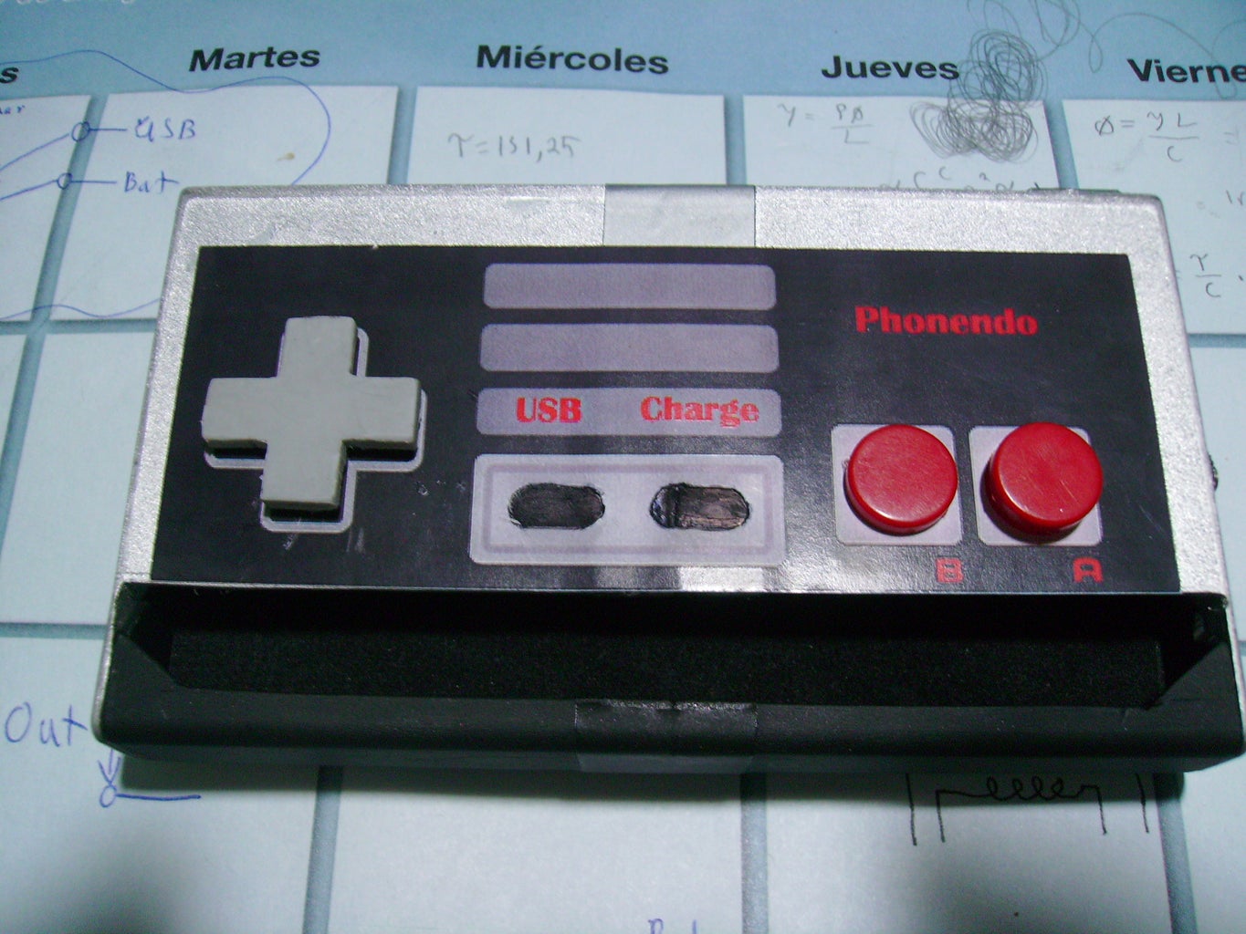
Step 11: Sticker, and Buttons


Print out the image of the NES controller on sticker paper, cut off were the buttons and leds go, and paste it.
Paint the top of the switches head with acrylic paint, or something like that, to mark were they will fit in the buttons. Then using the Moto-Tool, make a hole in the buttons, that dosent go through and is large enough to fit the switch head. Make sure you can press them all the way down and paste then with hot glue. Finaly, paint with a black marker the "USB" and "Charge" buttons, so they look like the original, but still can see the Leds when turn on.
Step 12: Enjoy


Finaly, I paste in the back of the case an old belt holder from an walkman, so you could use is in your belt when traveling, and charge your cellphone on the go. Also, it looks great.
P.D. It also looks great over my desktop with my old Sony portable speackers... :D

Participated in the
game.life challenge


