

Introduction: OldMan and Bluetooth


April 2020 Update, thanks to a comment from a reader, Krasla, I'm now able to get into command mode with JDY-31s.
Going to try to enter Sensor contest.
So this Lazy Old Geek (L.O.G.) just completed a GPS project:
https://www.instructables.com/id/Old-Man-and-the-Arduino-GPS/
and was thinking about ways to communicate with the GPS. Well, I had some old Bluetooth modules lying around and decided to see if I could get them working. Now these were HC-05/HC-06 Bluetooth modules that I may have sorted got working but not very good.
So I did a lot of Internet research. One of the best resources I found was Martyn Currey:
http://www.martyncurrey.com/hc-05-zg-b23090w-bluetooth-2-0-edr-modules/#more-5681
Step 1: Bluetooth Testing


So I started to do some testing. Many sites explained that these modules required 5V to power the device but 3.3V for TX and RX.
Most of these modules consist of a base Bluetooth soldered onto a Baseboard. See pictures
Sorry, I don’t have actual pictures as I soldered the one I had.
HC-05 HC-06 what’s the difference. Well, the HC-05 can be a master or slave, the HC-06 can only be a slave. What??? Well, in many cases you only need a slave like if you want to talk to your smartphone. You would need a master and a slave if you wanted them to talk to each other, e.g., one Arduino to another.
One of the minor problems is that the base HC-05 and HC-06 look almost identical. (I don’t know maybe they are physically the same except have different firmware.
So I have an old Arduino called a Seeeduino which is nice because it has a switch that sets it to either 3.3V or 5V. I hooked it up this way:
BT Seeeduino
Gnd Gnd
5V 5V
Rx 9 SoftwareSerial BTserial(10, 9)
Tx 10
Install BTTest.ino (Zip file)on Seeeduino
Basically what the sketch does is takes serial data from the Bluetooth and sends it out the serial port.
Now as documentation says, these modules have two modes, one is command mode where you can setup the module, e.g., Bluetooth name, password and baud rate (communication speed). Well, for this test I just wanted to see if I can talk command mode.
So after playing around with baud rates in the sketch, I found that setting both the Bluetooth and the serial port to 9600 baud worked.
Another important setup for my modules is that the Arduino Serial Terminal must be set to (no line ending) and all commands must be in caps.
TIP: in order to use command mode, the module needs to be unpaired. Most modules have an LED that blinks when unpaired and is solid when paired.
DISCUSSION: So many websites discuss this. Different modules may have different baud rates, (sometimes 38400) and different line endings. I believe it’s just how the designer set the software up when it was being made.
So I can send AT commands and the version comes up as linvorV1.5. I’m pretty sure both my modules are HC-06 and I was able to change the Bluetooth name. See picture
Here's some of the AT commands:
Command Response Comments
AT OK Communicating
AT+VERSION linvorV1.5 Identifies device and software?
AT+NAME OKsetname Apparently can change the device name
AT+PIN1234 OKsetpin There is no indication that it’s changing the password. Apparently you have to disconnect power for it to work
AT+PN None Sets serial parity to None
AT+PO Odd Sets serial parity to Odd
AT+PE Even Sets serial parity to Even
Attachments

Step 2: Bluetooth Testing 2


Okay, next step is to talk Bluetooth. So I have an Android smartphone and I tried an app called B-BLE. I couldn’t get it to work. Then I tried ‘Bluetooth Terminal’ This worked.
Procedure Smartphone
Go to Google Playstore and install Bluetooth Terminal.
Setup HC-06 with Seeduino (or CP2102) and connect to PC, open Arduino Serial Terminal.
On Smartphone, click on Settings, find Bluetooth, click on pair new device. If this is the first time you’ve connected you should see something similar this:
00:12:09:27:18:94
This is the HC-06s MAC address. Click on it
If not the first time, it will show the Bluetooth name, e.g., my2BT, click on it. See picture
It will ask you for Password, the ones I have are 1234. (If you have command access you can change the Password). See picture.
On Smartphone open Bluetooth Terminal app. It should open with Paired Devices screen, see picture,
Select the BT name, (my2BT).
By the way, this is where the BT module blinking LED should change to solid.
The Terminal screen should be displayed. See picture
Where it says “Enter ASCII Command”, type something to send to PC. Then tap (Send ASCII) (I have some of the BTNs programmed.)
The data entered should appear on the PC Arduino Serial Terminal. See picture
To send from PC, (I changed it to (both NT and CR) in command box, type what you want to send then click on (Send). It should appear on Bluetooth Terminal screen, see previous picture
Yay, we’re communicating!
Step 3: My Issue

As I mentioned before these modules are designed for 5V input and 3.3v signals. To me, this is the worst of both worlds. The proper way to use this is with a 5V Arduino, then convert the TX and RX levels to the correct ones. Some people use resistor dividers. Now I think my Seeduino even in 5V mode puts out 3.3V signals but other Arduinos don’t.
Now I am mostly using 3.3V devices like the Adafruit Feather M4 Express. The M4 Express does not have 5V power so how can I used these modules. One way is to use the bare HC-06 module without base but they’re harder to work with. What I decide to do was to convert my BT modules to 3.3V only. That’s what the big yellow 3 indicates.
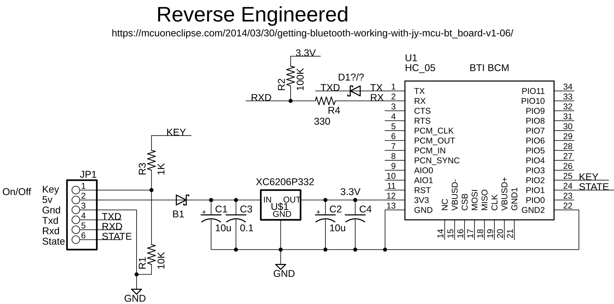
With some Internet help, I came up with a couple of schematic versions of the JY-MCU BT module see picture and put them in Eagle Cadsoft, see zip.
TECHNOBABBLE: The BTI BCM is the Bluetooth and the rest is the base board. Unfortunately, there are many different base boards. Some don’t have the B1 diode, some have a P channel mosFET to enable the device. But in this case the main problems are B1 and the 3.3V regulator. With a 3.3V input you wouldn't get 3.3V to the HC-06.
So I jumpered the VCC input pin (5V) to the 3.3V on pin 12 of the module. Now I think that’s all that’s needed but I also removed the regulator (XC6206P332, but could be different type). From a technical viewpoint, I don’t think it’s a good idea to basically short the input and output of a regulator. I'm not going to explain this in greater detail as each base board may be different. See yellow wire in the picture.
So now these modules will work on 3.3V systems.
Attachments
Step 4: Serial Adapter


So instead of using an Arduino on the PC, you can also use a USB-serial converter. The old Arduinos used the FTDI232 but they’re expensive, so I used to use PL2303 USB-serial converters. But since I couldn’t find a driver for the older models for Windows 10, I started using CP2102s. Now again the problem is the output pins all have 5V on them (coming directly from the USB connector). And there are many varieties. Anyway, I usually modify them for 3.3v and solder on a female header so it works with many of my Instructables projects. Now I also added a 3.3v regulator (L4931C33 I think) See picture. Most of the coverter ICs have a 3.3V output but I think most are limited to about 50mA. Actually, for just talking to the HC-06, 50mA is enough.
Okay so these can be hooked up to the HC-06 as follows:
BT CP2102
Gnd Gnd
3.3V 3.3V
Rx Tx
Tx Rx
See picture
Connect the CP2102 to PC USB. Now Arduino Serial Terminal is not the easiest to use so I tried Tera Term and Putty but they didn’t work very well, and I couldn’t figure out how to setup up for no line ending, so I’m still using Arduino. Works good.
Step 5: JDY-30/31 Bluetooth


So if you search on ebay for HC-06, they’re harder to find and you will often get JDY-30s instead. So since they seemed to be cheaper, I bought a couple actually from Aliexpress. They’re supposed to be compatible.
Some people and vendors claim that JDY-30 and JDY-31 are the same. I’m not so sure.
Anyway, the ones I got seem to be pin compatible and mine came on a similar base board as the HC-06.
Testing: April 2020 Update: Thanks to a comment from Krasla, I'm now able to connect to my JDY-31 in command mode. The main tip was that the "AT" command does not get a response but other commands like "AT+VERSION" works fine. And you do need to add CR + LF. Interestingly, I couldn't get this to work with Tera Term or Putty but it does work with Arduino Serial Monitor.
Anyway, so I decided to try this with Bluetooth. Using the same setup as the HC-06 I was able to connect with Bluetooth at 9600 baud.
Again the first time it is paired the device name will be a MAC address, but once paired the Bluetooth name is:JDY-31-SPP. Works good.
So I also found another BT called JDY-31, See pictures. What I like about them is that they have holes for a male header without needing a base board. See pictures. So I ordered a couple of these.
That’s my experience so far with Bluetooth modules.

Participated in the
Sensors Contest

![Tim's Mechanical Spider Leg [LU9685-20CU]](https://content.instructables.com/FFB/5R4I/LVKZ6G6R/FFB5R4ILVKZ6G6R.png?auto=webp&crop=1.2%3A1&frame=1&width=306)


