

Introduction: Raspberry Pi in the Wild ! Extended Timelapse With Battery Power


Motivation: I wanted to use battery powered Raspberry Pi camera to take once-a-day photos outdoors to create long term time-lapse videos. My particular application is to record ground cover plant growth this coming spring and summer.
Challenge: Design low current Raspberry Pi power control to ensure long battery life.
My Solution: I use a hacked alarm clock, Attiny85 circuit & Pimoroni OnOff shim to completely cut power to Raspberry Pi when not in use. While the Attiny85 and alarm clock continues running in standby mode, current draw is only 5 microAmps. Two AAA batteries power both Attiny and alarm clock, while a USB power bank powers the Pi.
Basic Operation: When to alarm clock goes off it wakes a sleeping Attiny circuit, which then signals Pimoroni OnOff shim to apply power from USB power bank to Raspberry Pi. The Pi executes a run-at-boot script (take a photograph). After sufficient time has passed (60 seconds in my application), the Attiny circuit again signals Pimoroni OnOff shim and then the Attiny enters sleep mode. Based on the signal from Attiny, the Pimoroni OnOff shim executes Pi shutdown command, and after Pi shutdown process completes, cuts power from USB power bank to Raspberry Pi.
Step 1: Parts and Tools


Parts:
Raspberry Pi Zero or Raspberry Pi Zero W (draws more power)
Raspberry PI Camera Module
Raspberry Pi Zero Case
Pimoroni ONOFF SHIM RASP PI POWER SWITCH, Digikey
OPTOISOLATOR Digikey
Battery Operated Digital Alarm Clock Target
ATtiny85 8 DIP Digikey
(2) CAP ALUM 100UF Digikey
DS3231 RTC Module AliExpress
(2) 68 ohm resistor
Short (about 6 inches) micro USB cable
Clear Box Amac SKU#: 60120. 4" x 4" x 5-1/16" h The Container Store
Kmashi 11200 mAh USB Power Bank # k-mp806 or similar
Double stick tape
Small self-tapping screw
(2) 1 X 8 pin female stacking headers - commonly sold a Arduino UNO stacking headers AliExpress
Perf or strip board about 1 1/4" by 2"
5 1/2 by 5 /12 by 3/4 thick pine or plywood
1 1/4 PVC pipe about 15 " long
1 1/4 PVC coupler
(2) short bungee cords about 10" long
(4) 1/4" dia. wooden dowel pins about 1"long
UltraDeck Natural Post Sleeve Cap Menards
Tools:
Wire Cutters and Solder Iron
Arduino UNO or other way to program ATtiny85
Hook up wire and jumpers
Keyboard, mouse, HDMI monitor, USB port and Ethernet Hub , OTG cable
Mulitmeter
Step 2: Install Raspberry Pi OS, Pimoroni OnOff Shim, DS3231 RTC, and Pi Camera Module


Pi Zero setup. Prepare SD card for Raspberry Pi with the distribution of your choice. During initial setup process, being sure to enable I2C interface, camera, and boot to CLI with auto login, set the correct local time and change your password. I also recommend setting up a Static IP Address to make things easier down the road. Solder male header to Pi Zero. You can use either the standard 2 x 20 header or a shorter 2 x 6 header, as all 40 pins are not required for this project - just the first 12 pins.
Camera Install. Snap Pi Zero into its case and use the included short ribbon cable connect camera module to Pi Zero routing the cable out case end slot. Fit the GPIO slotted top cover and attach the camera to the cover with double stick tape (see photo).
Prepare Pimoroni OnOff Shim, DS3231 RTC. Although the Pimoroni OnOff Shim comes with a 2 x 6 female header I instead used two 1 x 6 female "stacking headers commonly sold for Arduino UNOs, The header pins need to extend above the Pimoroni OnOff Shim at Raspberry Pi pin locations 1, 3 ,5, 7, 9, the other pins can be cut down to standard pin length. Push the DS3231 RTC onto the extended pins as shown in the photo and then push the Pimoroni OnOff Shim & DS3231 RTC sub-assembly onto the Raspberry Pi header pins as shown.
Install Pimoroni OnOff Shim software with:
curl https://get.pimoroni.com/onoffshim | bash
For additional info on installing Shim look here
Install DS3231 RTC software per these instructions
Initial Tests - Camera,Pimoroni OnOff Shim, DS3231 RTC
Connect local keyboard and monitor to Pi Zero. Ensure you have a network connection (ethernet cable or Wifi). Connect USB power cable Pimoroni OnOff Shim.
a. Press Pimoroni OnOff Shim push button for 3 seconds and then release - this toggles the Pi Zero on or off. Observe the bootup and shutdown process on the monitor. Your Pi Zero now has a advanced technology upgrade - an on/off switch!
b. Set DS3231 time and verify it reads out the correct time with:
sudo hwclock -w

sudo hwclock -r
c. Test camera function per these instructions.
Step 3: Setup Up Raspberry Pi Run-At-Boot Script and Test Camera

Create and move into new zerocam subdirectory
mkdir zerocam
cd zerocam
Use nano editor to create new script file
nano photo.sh
Then copy and paste the below code into the nano editor. The close nano with Ctrl+X, Y then Return.
#!/bin/bash
DATE=$(date +"%Y-%m-%d_%H%M")
raspistill -o /home/pi/zerocam/$DATE.jpg
convert -pointsize 80 -fill yellow -draw "text 570,1800 '$(date)'" /home/pi/zerocam/$DATE.jpg /home/pi/zerocam/$DATE.jpg
Since this script uses the convert command, you'll need to install ImageMagick on the Raspberry Pi
sudo apt-get update
sudo apt-get install imagemagick
Make the file executable
chmod +x photo.sh
Open /etc/rc.local (commands in this file run at boot)
sudo nano /etc/rc.local
Near the bottom of the file, just before exit 0 statement add this new line and then close nano with Ctrl+X, Y then Return.
sh /home/pi/zerocam/photo.sh
With a local monitor connected, test that it works
sudo reboot
The Pi should reboot and take a photo. There will be a new .jpg file in directory /home/pi/zerocam
Also test turning the Pi on and off with Pimoroni push button. Measure and record the Pi boot up time. It should less than 60 seconds.
Step 4: Hack Alarm Clock


Observe as produced operation - Install two AAA batteries in alarm clock, and practice setting time and alarm per the included instructions. In particular observe the alarm sounding - you should see the (1) the display's little alarm symbol flashing, (2) the buzzer sounds for 1 minutes then shuts off and (3) the back light LED illuminates for 5 seconds then turns off.
Disassemble - Remove the four screws from clock back to separate the two halves, then remove four more screws to free the main PCB.
Hack - Cut the LED leads at the front of the PCB as shown and solder to 5" long wires to the remaining leads on the backside of the PCB (see illustration). Desolder the buzzer as shown.
To the battery compartment terminals add two additional wires (red and black) plus an 100MFD electrolytic capacitor as shown (observe polarity).
Reassemble the clock making sure to route LED and new battery leads out the rear cover retention slots as shown.
Retest - Install batteries and test the alarm function - now when the alarm goes off you should see the display's little alarm symbol flashing - but no buzzer and no backlight. Connect a mulitmeter to LED leads you should detect about 3 VDC when the alarm goes off of a period of about 5 seconds..
Step 5: Build Attiny85 Circuit Board


Referring to the photo and Attiny85 Schematic.pdf construct the circuit board on a small piece of perf or strip board. Notes:
- Be sure to use a 8 pin DIP socket for Attiny85 chip as it needs to be removed for programming.
- Assure correct orientation of the Optos before soldering.
- Jumper leads to Pimoroni Shim should be at least 4 inches long with female headers to attach the the Shims BTN male pins.
- Observe Polarity when making connections with alarm click - circuit has no reverse polarity protection
Attachments

Step 6: Upload Code to Attiny 85 Chip
Using an Arduino Uno or other means, upload the code (AttinyPiPowerControl.ino file attached) to your Attiny85 chip. Note - this code allows 60 seconds for the PI to boot up, take a photo and get to terminal command prompt before starting the shutdown process. You can then install the Attiny85 chip in its circuit board socket - double check orientation.
Note: If you need more or less Pi runtime, just edit this line near the bottom:
delay(60000); // let Pi boot and run for a time
Attachments

Step 7: Wiring and Initial Test and Downloading Photo Files From PI

Wiring:
Connect USB power bank to micro usb port of Pimoroni shim. Connect jumper leads from Attiny85 circuit board to Pimoroni shim, ensure the black lead connects to the outermost edge BTN pin on Pimoroni shim.
Test:
Install 2 AAA batteries in alarm clock, and set clock time. I recommend also connecting Pi's HDMI port to a local monitor.
Turn the Alarm on and set an alarm a few minutes into the future. When the alarm goes off, you should see:
a. Clock alarm icon starts flashing
b. After about 5 second the Pimoroni Shim red LED comes on for 5 seconds
c. The Pi starts booting up
d. After about 20 seconds the camera LED comes on and a photo is taken. If you have a local monitor connect, you'll see a brief preview of the photo taken.
e. After another 40 seconds or so, the Pi boots all the way up to terminal command prompt
f. Pi starts the shutdown process, after about 20 seconds the Pimoroni Shim red LED flashes indicating power is cut to the PI
Downloading photo files from PI
I connect the PI to my network using OTG cable, and USB to ethernet adapter, powering Pi from wall wart. Then use WinSCP to download files to my PC.
Step 8: Assemble Electronics Enclosure


Attach Attiny85 circuit board to back of alarm clock using a small self-tapping screw. Attach PI to clock using double stick tape as show.
Attach clock left side to display case bottom with double stick tape.
Attach USB power bank to display case bottom with double stick tape as shown.
Place the top case over the display case bottom as shown.
Step 9: Construct Mounting Stake, Final Assembly and Release PI Into the Wild


Bottom piece: In a 5 1/2 X 5 1/2 piece of wood, cut 4 slots 3/4" inward from each side as shown. I used a 1/4 router bit, but you can also drill and saw. In the center make a hole for 1 1/4 PVC coupling. Ideal hole size is 1 5/8", but since I only had a 1 3/4" hole saw, I used that and built up coupling OD with duck tape. Glue coupling in place with epoxy.
Center the electronics enclosure above the wood block and mark its outline. Then drill four 1/4 holes along each side as shown. Glue four 1" long 1/4" dia wood dowels in these holes - this will help keep the enclosure centered.
Top piece: drill four 3/16" holes near the lower edge of each size and insert 3/4" long S-hooks in each hole bending the ends closed so they won't fall off. On the inside edges hot glue 4 four 1/2 thick scraps of wood - these will help keep the top piece centered above the enclosure.
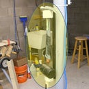
Final Assembly: Sandwich the electronics enclosure between top and bottom pieces and secure with two bungee cords as shown.
Release PI into the Wild: Make a mounting stake by cutting 1 1/4" PVC pipe of a length suitable to your purposes, cut one end at a 45 degree angle to make it easier to pound into the ground. In my case I'm interested in ground cover plant growth (Vinea minor) this spring and, so my PVC stake is only 15" long. Double check that AAA batteries are fresh,USB power bank is fully charged and alarm clock is properly set - then pound stake into the ground and slip assembly on top of mounting stake - see photo.
Step 10: Current Measurements and Accelerated Battery Life Test


I measured current using Radio Shack RS-232 Multimeter (22-812) and companion Meter View software. Not the beast choice, but it's what I have.
Measurement of current draw from two AAA batteries power Attiny85 board and alarm clock
To "series connect" multimeter, I used dummy batteries and 3 VDC bench power supply (see photo). See graph of current measured during the "active" period (begins with alarm event - ends with Attiny85 returns to sleep mode). Non-alarm draw was constant 0.0049 mA. Summary -
Active Period = 78 seconds
Active Period Avg. Current = 4.85 mA
Non-Alarm Current = 4.9 microA (0.0049 mA)
I calculated an average daily current draw of 0.0093 mA from the two AAA (750 mAh/each) considering the sleeping and active modes, and theoretical battery life > 8 years using this method .
Measurement of PI current draw from USB powerbank.
To "series connect" multimeter I used a modified usb cable (see photo). See graph of current measured during the "active" period (PI boot up - PI shutdown). During non-active period the Pimoroni ONOFF shim completely cuts power to Pi, so current draw ~ zero. Summary -
Active Period = 97 seconds
Active Period Avg. Current = 137 mA
Assuming a 11200 mAh power bank the theoretical number of active period cycles is > 3000.
Accelerated Battery Life Test
I temporarily controlled the PI with Arduino UNO programmed for rapid cycling - the time between alarms was 2 minutes vs. the normal 24 hours.
Test #1: 11200mAh power bank. Started at 10 PM and I halted at 1 PM the following day. Results: 413 photos taken, 3 of 4 charge level LEDs still on at test's end.
Test #2: 7200mAh power bank. Started at 7:30 PM and I halted at 4:30 PM the following day. Results: 573 photos taken, 2 of 4 charge level LED still on at test's end.
Conclusion: I believe the above results indicate at least a year's operation taking 1 per photos is likely.


