

Introduction: Reverse Parking Assist in the Garage Using Existing Safety Sensor and Analog Circuit


I suspect that many inventions in the history of mankind were made because of complaining wives. Washing machine and refrigerator do certainly seem like viable candidates. My tiny "invention" described in this Instructable is an electronic garage parking assistant that is also a result of (yes, you guessed it) wifely complaints. :)
I like parking my car in our garage in reverse for fast exit in the morning. If I park it too far, my wife is unhappy about narrow passage to home's door. If I park it not far enough, then the front bumper is in the way of remotely controlled garage door. The ideal spot is to have front bumper 1-2 inches from the closed door, which is quite hard to achieve every time.
Naturally, the simplest solution is the classic tennis ball on a string hanging from the ceiling. Sure, it would work, but where is the fun? For an electronic hobbyist like me the first thought is building a circuit! There exist at least dozen Instructables describing garage range finder based on an ultrasound sensor, Arduino, and some kind of light signal using LEDs. Hence, to make it more interesting I opted for an alternative solution that takes advantage of an existing safety reversing sensor that is an integral part of automatic garage door manufactured by LiftMaster. The following video explains how it works, saving me a lot of writing.
Sensor's receiver signals "all clear" the moment front bumper stops intersecting the infrared beam. Perfect! All I have to do is to intercept this signal, right? Well, it's easier said than done...
(Disclaimer: By proceeding to the next step you acknowledge that you are well versed in electronics and are well aware that this project tinkers with an existing safety equipment. It works fine if done correctly, but if you screw something up you risk rendering the said safety equipment ineffective. Proceed at you own risk, I shall not be held liable for any ill effects, such as dead/injured pets, kids, etc., resulting from your implementation of this Instructable.)
Step 1: Problem 1: How to Intercept and Utilize Signal From LiftMaster's Safety Sensor?


When path of the infrared (IR) beam between emitter and receiver is clear, the receiver sends through a pair of wires a 156 Hz square wave signal as shown in the first image. In a single period 6.5 ms of ~6 V high is followed by no more than 0.5 ms of ~0 V low (second and third image). When the IR beam meets an obstacle, the receiver sends no signal and the line remains high at the supply voltage (fourth image). Interestingly, power supply for both emitter and receiver, as well as receiver's signal, originate from a single pair of terminals in the back of LiftMaster opener (fifth image).
Thus, the essence of this problem is how to detect the square wave signal in the 1st image from the DC signal in image 4. There is no need to reinvent the wheel, since this problem has been solved by others with a Missing Pulse Detector circuit. There are many implementations; I have picked one from this Circuits Today page and slightly modified it as shown in the fifth image. The original page describes its principles of operation in detail. In short, the NE555 timer operating in monostable mode will keep its OUTPUT pin high as long as the period of the incoming square wave (connected to TRIGGER) is shorter than the timing interval on THRESHOLD+DISCHARGE pins. The latter depends on the values of R1 and C2. A DC voltage on TRIGGER will allow C2 to charge above threshold value and the OUTPUT pin will go low. Problem solved!
Step 2: Problem 2: How to Visually Indicate the State of Timer's OUTPUT Pin?

This is a no brainer: use an LED. Keep it off when the IR beam is intact and OUTPUT is high (which happens 99.999% of the time) and turn it on when the beam is interrupted and OUTPUT goes low. In other words, invert OUTPUT signal to power the LED. The simplest switch of this kind, IMHO, uses a P-channel MOSFET transistor, as shown in the above image. Timer's OUTPUT is connected to its gate. As long as it is high, the transistor is in high impedance mode and the LED is off. And vice versa, low voltage on the gate will enable current to flow. The pull-up resistor R4 ensures that the gate is never left dangling and kept at its preferred state. Problem solved!
Step 3: Problem 3: How to Power the Circuit Described So Far?

The Missing Pulse Detector shown in Step 1 needs a steady DC supply voltage. I could use batteries or buy a suitable AC/DC adapter. Meh, too much trouble. How about using the safety sensor's supply itself provided by LiftMaster? Well, the problem is that it carries the IR receiver's signal, which is neither "steady", nor "DC". But it can be properly filtered and smoothed with a very simple circuit shown above. A large 1 mF electrolytic capacitor is a good enough filter and the attached diode makes sure it does not discharge back when the signal is low. Problem solved!
The trick is not to draw too much current from LiftMaster, or else the safety sensor operation may be compromised. For this reason I did not use the standard NE555 timer but its CMOS clone TS555 with very low power consumption.
Step 4: Problem 4: How to Put All the Components Together?


Easily; see the complete circuit above. Here is the list of parts I used:
- U1 = Low power single CMOS timer TS555 made by STMicroelectronics.
- M1 = P-channel MOSFET transistor IRF9Z34N.
- Q1 = PNP BJT transistor BC157.
- D1 = Diode 1N4148.
- D2 = yellow LED, type unknown.
- C1 = 10 nF ceramic capacitor.
- C2 = 10 uF electrolytic capacitor.
- C3 = 1 mF electrolytic capacitor.
- R1 and R2 = 1 k-ohm resistors.
- R3 = 100 ohm resistor.
- R4 = 10 k-ohm resistor.
With 5.2 V supply the above circuit consumes only ~3 mA when LED is off and ~25 mA when it's on. The current consumption can be further reduced to ~1 mA by changing R1 to 100 k-ohm and C2 to 100 nF. Further increase in resistance and reduction in capacitance constrained by keeping the RC product constant (=0.01) does not reduce current.
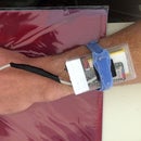
I have placed the LED and R3 resistor in a cute little Altoids tin and nailed it to the wall. From it, I ran a long cable all the way to the LiftMaster opener on the ceiling. The driver circuit was soldered on a general purpose board and placed in a cute little box I got from Adafruit. The box is attached to the LiftMaster's frame and the pair of supply wires is attached to the safety sensor terminals.
While backing my car into the garage I stop as soon as the LED turns off. The result is a perfect alignment, as shown in the last image. Problem solved!
Step 5: Addendum: Lighter, Although Not Brighter Parking Assistant :)


10 days after this Instructable was first published, I built the guiding parking light for my second garage door. It is worth mentioning here since I have made small improvements in the circuit design. See the first image. First, I opted for lower current option for the RC pair described in the previous step where low capacitance of 100 nF matches higher resistance of 100 k-ohm. Next, I eliminated the PMOS transistor and 10 k-ohm pull-up resistor and connected the LED ground directly to the OUTPUT pin of TS555. It is possible because an object in the path of the IR beam brings the OUTPUT voltage low, effectively turning the LED on. There is a price to pay for this simplification, though. With PMOS present I didn't have to worry about LED current: IRF9Z34N can take 19 A, so the LED can shine as bright as I want it to. The OUTPUT pin of TS555 can sink only 10 mA, hence I had to pair the LED with a higher resistor of 220 ohm, which lowered its brightness. It is still well visible, as the fourth image shows, so it works for me. The list of parts for this design is as follows:
- U3 = Low power single CMOS timer TS555 made by STMicroelectronics.
- Q3 = PNP BJT transistor BC157.
- D5 = Diode 1N4148.
- D6 = yellow LED, type unknown.
- C7 = 10 nF ceramic capacitor.
- C8 = 100 nF ceramic capacitor.
- C9 = 1 mF electrolytic capacitor.
- R9 = 100 k-ohm resistor.
- R10 = 1 k-ohm resistor.
- R11 = 220 ohm resistor.
The circuit consumes 1 mA and 12 mA in its OFF and ON state, respectively.

![Tim's Mechanical Spider Leg [LU9685-20CU]](https://content.instructables.com/FFB/5R4I/LVKZ6G6R/FFB5R4ILVKZ6G6R.png?auto=webp&crop=1.2%3A1&frame=1&width=306)


