Introduction: Self-Stirring Cauldron From Harry Potter


With the release of J.K. Rowling's The Cursed Child and the recent Harry Potter themed Wizarding contest here on Instructables, there has never been a better time to create my first Harry Potter themed project. All I needed was an inspirational idea.
Fortunately my girlfriend came up with the wonderful suggestion of making the self-stirring cauldron. It was something that immediately captured my imagination and to my surprise there wasn't an Instructable for one, so I started work on it right away. The brief was simple, a cheap but effective cauldron with working stirring action and some visual effects. The result was a project that can be made for under £20 (around $25), and overall I'm pretty pleased with it.
For anyone who is not familiar with the Self-Stirring Cauldron, it appeared in Harry Potter and the Philosopher's Stone. It was invented by Gaspard Shingleton and was sold in cauldron shops to assist the owner in the stirring of his or her potions. But of course, you could always use a potion stirring charm. The cauldron also has a choice of three stirring actions, making it suitable for mixing almost any potion.
The cauldron forms the centrepiece in a Harry Potter themed potion mixing room scene that I've made, I'll be posting the Instructable for it soon so remember to check back for updates...
Your comments and questions are always appreciated so let me know what you think.
Step 1: Things You'll Need

The Cauldron is made up of four main elements, the Stirring Action (we'll be using a stepper motor for this), the Lighting (LED strip lighting) and the visual Fog Effect (here we'll be using dry ice, more on this later) ohh and of course the Cauldron (ideally a witchy type one but you can use anything you can get your hands on, I hear saucepans are all the rage amongst muggles!).
Below is a list of fantastic bits and where to find them:
28BYJ-48 Stepper Motor with ULN2003 Driver Board
£1.99 on Amazon UK or $2.99 on Amazon USA
5v LED Waterproof Light Strip RGB
£7.99 on Amazon UK or $4.37 on Amazon USA
PICAXE 14M2 Microcontroller
£1.80 from the PICAXE UK Store or $3.95 from Sparkfun USA(don't forget your PCB mounting IC socket). If you've never used a PICAXE before check out the getting started guide.
Copper Board or Veroboard / Stripboard
This Instructable uses an etched copper PCB (layouts are provided in the Ible) but feel free to use stripboard. If you've never etched your own PCB before why not give it a go, there are plenty of helpful Instructables. I'd recommend DIY Customized Circuit Board by ASCAS.
Various Electronic Components
If you're in the UK I'd recommend RS Components, I guess that over the pond Digi-Key are pretty good too.
- 1x 100nF Capacitor
- 1x 4k7 Resistor
- 2x 1k Resistor
- 2x BCX38C Darlington Transistor
- 1x On/Off Toggle Switch
- 1x Box for 3x AA Batteries
- 2x 2-Way Pin Headers (2.54mm pitch)
- 3x 2-Way Header Connectors
- 1x 4-Way Header Connector
Tip:I salvaged all of my header connectors from a scrap PC.
Fixings
You'll need 2x M3 x 13mm Pan Head Screws and 2x M3 Hex Nuts.
Wooden Spoon Handle
Why not treat yourself to a nice new wooden spoon, use the old one here.
Enclosure / Case and Stirring Mechanics
I often use 3d Printed parts to quickly prototype my designs and this project is no exception, the STL files are provided with the Instructable.
I understand that it can be frustrating for makers who don't have access to certain equipment, but don't despair! The mechanics (outlined in step 3) can be replicated by using alternative methods, if you can salvage cogs or wheels from scrap items such as an old printer you'll be halfway there. It's also worth keeping in mind that where specialist equipment such as 3d printers are not available you can always use 3rd party services like 3d Hubs. Alternatively you could consider finding a HackSpace near you, these are great ways to meet like-minded makers and it gives you access to a broader range of tools and equipment.


Step 2: The Electronics - LEDs


We have to start somewhere so it might just as well be where the magic truly happens, the electronics. This is divided into three main parts, the LEDs, the stepper motor and the circuit. I'll walk you through the three parts individually then we'll bring them all together at the end.
The LEDs
For the lighting we are using a SMD 5050 light strip. These are really versatile light strips that are bright, offer RGB colour and can be cut to the desired length. As water is also used in this project I'd recommend getting the waterproof ones. The strips often come in kits that include a controller, you can put that to one side for another day as we don't need it, ours will be driven by a PICAXE microcontroller.
Cut the Strips
To begin with we want to cut our strips to the correct lengths, they are typically divided into blocks of 3x LED's. We want two identical length strips of 4x blocks (12x LEDs per strip). The strips have a line to indicate where to cut them (usually in the middle of the copper contact pads) and can be done using a scissors.
Preparing the Cables and Connectors
For this I salvaged some cables with 2-way header connectors from a scrap PC (they are used to connect the PC front panel to the mainboard). Cut the cable to around 70mm length (connector included) then strip and tin with solder as shown in the photos provided.
Solder the Cables to the Light Strip
The light strip has copper contact pads on each end, this is where you will make your connections. The waterproof strips will usually have a plastic or rubber coating on the surface so this will need to be removed from the pads by simply peeling or breaking away. Once the copper is exposed it's a good idea to lightly rub it with a fine sand paper, this will help take the sheen off the copper and provide a better bond for the solder.
You'll notice that each copper pad will be labelled as +5v and R, G, B. The RGB are the negative (-) terminals, whereas the 5v is the positive (+) terminal. The RGB should indicate the colour, though in the case of my strip it was lying to me, green and blue were the opposite of the markings so probably a good idea to test it before soldering. For this project I'm just using the colour green.
Solder the prepeared wires to the pads on the strip (as show in the photos), taking care to wire up the cable colours to indicate the polarity. I finish off by using hot-melt glue to act as a strain relief.
Step 3: The Electronics - Motor

To create the stirring effect we are using a stepper motor, I've opted for the 28BYH-48. These motors are manufactured in large volumes so they are so cheap they're practically giving them away. They are known for missing the occasional step so not great for high precision tasks, but they are small and provide a lot of torque thanks to its 64:1 gear reduction ratio. You can read more about this motor here. The motor is commonly supplied with a ULN2003 driver, which is perfect for using with our PICAXE. The motor control is covered in more detail in the next step when we program the PICAXE.
Connecting the Stepper Motor to the ULN2003 Driver Board
The motor has a 5-way connector that simply fits into the header on the driver board, the cable is a little longer than we need but not enough to cause any issues.
Connecting the ULN2003 Driver Board to the PICAXE
As with the previous step we'll again be turning to a scrap PC for parts, this time we need a 4-way connector as well as another 2-way. The 4-way connects to the IN1, IN2, IN3 and IN4 header, while the 2-way connects to the 5-12v header (the driver needs to be connected directly to the power source, more on this in the next step). On the PICAXE side the 4-way cables will be soldered to the custom PCB.
Step 4: The Electronics - Circuit


Now here comes the fun part, the circuit. To complete this step you will undertake the following tasks:
- Make the Circuit (as outlined in the schematic)
- Program the PICAXE Chip (code provided)
- Solder the four ULN2003 Motor Driver connections (as indicated in the photos)
- Connect the Motor Driver to the power source
- Hook up an on/off switch
- Testing
1. Make the Circuit
Ever since I discovered the joys of etching my own PCB I never miss an opportunity to make one, so if you're well practiced you could probably churn out the whole circuit in under an hour. I've included the PCB file as well as ready to print PDFs of the PCB layout. If you're stripboarding I've also provided the circuit schematic for you to follow.
For this task you will need the following components:
- 1x 100nF Capacitor
- 1x 4k7 Resistor
- 2x 1k Resistor
- 2x BCX38C Darlington Transistor
- 1x On/Off Toggle Switch
- 1x Box for 3x AA Batteries
To summarise, we have a PICAXE directly controlling the Motor Driver board via four outputs. The PICAXE is then switching a pair of darlington transistors via another two outputs to control the LEDs. We have a switched 4.5v battery source (3x AA's) feeding the PICAXE, the LED strips and the Motor Driver. Don't be fooled by the PP3 connector in the photos, this does not connect to a 9v PP9 battery!! It connects to a AA battery box.
2. Program the PICAXE Chip
The motor and the lights are controlled by the PICAXE microcontroller, to achieve this we use two separate programs that run as parallel tasks on the PICAXE (I believe this is only possible with the newer M2 chips).
The motor uses a very simple code that rotates it at a set speed in a clockwise direction using the half-step method. If you want to read more about stepper motors, check out the How to use a Stepper Motor Instructable by JColvin91.
For the lighting we are doing something a little more fancy. To give the visual effects an organic feel we won't be flashing or fading our lights, but flickering them randomly in an attempt to mimic a candle. To achieve this we are using PWM (Pulse Width Modulation) and a bit of code that randomises the PWM signals. To further enhance the effect the two light strips are flickering randomly independently of each other. When the light is diffused it creates a really authentic look (I've provided a video of the flickering lights).
The complete code for the PICAXE is provided below, copy and paste this to the PICAXE Editor software and program your chip. If you are new to PICAXE I'd recommend you invest some time in familiarising yourself with it. It's really straight forward and it will revolutionise your projects, opening the door to a whole new world of possibilities. Programming them is easy and PICAXE provide comprehensive instructions and manuals, find out more here.
start0:
	cw:
  	high 2
  	low 3
 	low 4
	low 5
	pause 5
	high 2
	high 3
	low 4
	low 5
	pause 5
	low 2
	high 3
	low 4
	low 5
	pause 5
	low 2
	high 3
	high 4
	low 5
	pause 5
	low 2
	low 3
	high 4
	low 5
	pause 5
	low 2
	low 3
	high 4
	high 5
	pause 5
	low 2
	low 3
	low 4
	high 5
	pause 5
	high 2
	low 3
	low 4
	high 5
	pause 5
	goto cw
	stop

start1:
	do
	symbol led_1_brightness         = w0
	symbol led_2_brightness         = w1
	symbol pausetime            = b6
	symbol spool                = b7
	symbol pause_mod            = w2

	led_1_brightness = 300
	led_2_brightness = 500

	Main:
	pause_mod = time + 700
		for spool = 1 to 8
			random pausetime
			random Led_1_brightness
			random Led_2_brightness
			next
	let Led_1_brightness  = Led_1_brightness    // 351 + 50
	let Led_2_brightness  = Led_2_brightness    // 300 + 50

	pwmout c.0, 99, Led_1_brightness
	pwmout c.2, 99, Led_2_brightness

	let pause_mod = pause_mod // 21
	let pausetime = pausetime // 15 + pause_mod

	pause pausetime
	goto main
	loop
	stop
The LED flickering code was developed by Steve O and was posted on the GOE (Garage of Evil), so credit to Steve for sharing his awesome work.
3. Solder the four ULN2003 Motor Driver connections
For this step you just need to follow the guide in photo three, it connects four PICAXE pins to the Motor Driver header cable that you made in the last step. It uses the following pin configuration:
- PICAXE B2 --> ULN2003 IN1
- PICAXE B3 --> ULN2003 IN2
- PICAXE B4 --> ULN2003 IN3
- PICAXE B5 --> ULN2003 IN4
4. Connect the motor to the power source
As the motor requires more current than the microcontroller is able to handle we need to connect the ULN2003 directly to our power source. You may have noticed that the motor is rated at 5-12v and our battery source is only providing 4.5v, don't worry, it's more than enough to drive the motor.
As you'll see in one of the photos I connected my motor power in parallel with the power input on the circuit, but you could also wire the +5v at the switch side and ground it to the battery box if you prefer.
5. Hook up an on/off switch
To make switching on and off easier without the need to disconnect the battery you'll want to hook up a toggle switch. I retro-fitted mine by connecting it between the positive terminal on the battery and the circuit, then gluing it to the back end of the enclosure (we'll be covering the enclosure and assembly in the next step).
6. Testing
Once the LEDs, motor and circuit have all been made it's time for testing. Hook things up and test one item at a time. Hopefully everything will work for you but if you encounter any problems, double-check all your connections, get the multi-meter out, and check the schematic. Once you are happy everything is working it's time to move on to the next step... Assembly.


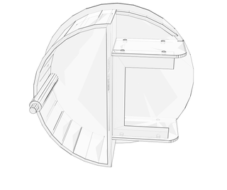
Step 5: Enclosure and Assembly


Now that you have the electronics, lights, motor and battery all prepped we are ready to assemble. Included is an exploded diagram of the assembly pieces, you should be able to work out how it all goes together by following the images, but I'll take you through it step by step as well. I printed all of my 3d parts using 50% infill and a 0.1 layer height, but you will get away with a lower infill and a greater layer height. As long as the water tanks remain water tight you will be fine, there is no physical stress placed on any of the parts when in use.
Tip:If you don't have access to a 3d printer you can simplify the mechanical assembly by salvaging a large cog or wheel from a scrap printer. Fix this to the motors drive shaft then glue on your spoon, simple!
Attach the LED Light Strips
The light strips are self-adhesive, peel back the protective covers to reveal the adhesive layer and apply them to the front curve of the main enclsoure. Make sure that you fix them in the same orientation so that both sets of wires are on the same side, this will dictate where your custom circuit PCB is located.
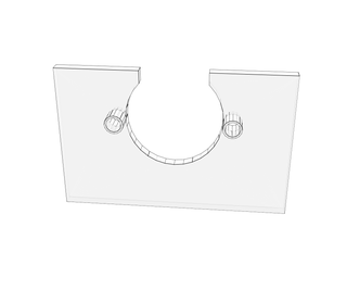
Motor and Drive Plate Assembly
- First you'll want to fix the step motor to the motor assembly plate, this is done using the M3 screws and nuts.
- Fix the motor assembly to the main enclosure, it sits on the shelf supports and superglues in place.
- The drive plate assembly consists of two pieces that are glued together. Make sure that the centers are aligned to allow the motor shaft to fit. You may need to use a countersinking tool to make a recess in the base of the smaller plate, this will allow the assembly to slide further down the motor shaft if necessary.
- The drive plate assembly push fits by slotting onto the motor shaft.
Electronics Assembly
- The circuits are fitted to either side of the main enclosure, there are pilot holes to enable the PCB's to be screw mounted, but I opted to use hot-melt glue to secure mine.
- The cables can been hidden in the battery recess below the motor assembly, I used a cable tie with a self-adhesive tie mount to keep them in place.
- Slide the battery box into the recess.
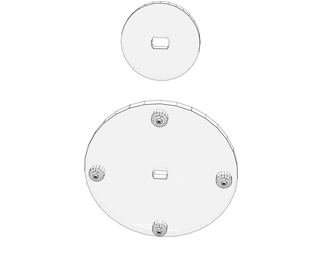
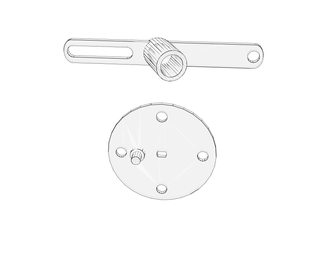
Stirring Actions
Choose one of the three stirring action pieces and slot it onto the drive plate. Line up the four pins and it should slot on securely. If the fit is too tight, use a round file to make the holes on the action plate a little larger.
Note that Stirring action three consists of two pieces, the round plate and the arm. The slotted section of the arm sits in the pin located at the front of the enclosure, while the hole fits onto the round plate's pin.
Water Tank
The crescent shape on the front of the enclsoure is a water tank, it also has a Max Fill level marker for your reference. This can be used for the purpose of adding a fog effect to your cauldron with the aid of some dry ice (more on this in the next step). Included with the STL files is the water tank assembly. This consists of a removable tank that has a carry handle to make filling and emptying easier. Just glue the handle bar in place and it can be used to lift the tank in and out.
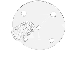
Wooden Spoon
You'll want to take your wooden spoon and remove the spoon-end with a saw, leaving you with just the handle. The stirring action pieces have a cylinder fitting on them designed to secure your spoon handle in place. It should simply just slot-in. If you find that your spoon handle is too large, sand down one end until it fits comfortably but firmly in the holder.
The Cauldron
To improve the effectiveness of the light effects you'll want to line the inner walls with some tin-foil. Cut a suitable length to cover the circumference of your cauldron, then put it inside and push it out into the edges.
First test...
Drop your completed assembly inside the cauldron and switch-on. To secure it in place I used some self-adhesive velcro strips, this stops the assembly sliding around when the cauldron is moved.
Tip: To enhance the visual effects I used dry ice to create a misty fog effect, this is covered in the next step.
Step 6: Visual Enhancements - Dry Ice
Now that you have your self-stirring cauldron up and running it's time to turn things up and add some extra special effects and visual enhancements. To achieve this we will be using dry ice, this will create a smoke-like misty fog effect that will pour over the edges of the cauldron, also diffusing the flickering LEDs. Dry ice can be obtained from specialist dry-ice suppliers, but in the USA it is sometimes sold by Wal-Mart and CostCo as well. I'd recommend using dry ice pellets instead of sheets as it is easier to handle.
Note:Dry ice is extremely cold and can be dangerous, please take all necessary precautions when handling and using, for more information read the dry ice safety information on DryIceInfo.com.
Using the Dry Ice
Note:When handling the dry ice always use insulated gloves, it's -80°C (-176°F) and has the potential to cause frost bite.
- Take some dry ice pellets and place them in the removable water tank.
- Slot the water tank into place.
- Fill the water tank with warm water, I use a funnel to minimise spillage.
- Switch on the cauldron and admire the rising green glowing fog, mixing your wickedly marvellous potions.
Tip:The hotter the water the better the smoke effect.
I hope you like the Ible, thanks for reading!

Third Prize in the
Halloween Decor Contest 2016

Second Prize in the
Wizarding Contest

Participated in the
Maker Olympics Contest 2016