

Introduction: Simple 3D Printed Chassis


Background
This Instructable is about a simple 3D printed chassis I made as a test base for a robotics platform. I tried to make it have as few non-printed parts as possible, to maximize the number of people who would be able to use it. I printed it all in ABS plastic, and it has held up well--no broken parts yet!.
Uses
This chassis could be used as a simple RC car, or for some robotics platforms(I built it to test vision processing with a Raspberry Pi). Also, with its high speed, this could even be used to race each another robot!
Limitations
Because I only used a single stage gearbox, this bot is FAST. Once the gears wear in, it can be run smoothly with low voltages, but it does not have much torque to pull weight or to drive slowly.
This base is also very short and wide, as the application I designed it for required this. If too much weight is added high up, it can become easy to tip. However, it can right itself easily. In fact, if you placed all controlling electronics next to the motors, and not on top, this robot could flip upside-down and still run just fine.
Step 1: Materials


Printed parts: can be downloaded here or at my Thingiverse page. Print in ABS for best durability.
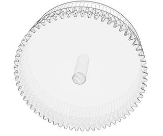
-4x Wheels
-2x Gearbox
-1x Cross brace
-2x Cross support
-2x Pinion gear
Non-printed parts: can be obtained from McMaster-Carr, or other hardware supplier
-2x RS-550 motors, or motors with same shaft/ mounting setup(bought from BaneBots, not McMaster-Carr)
-8x bushing, 1/4" ID, 3/8" OD, with lip
-4x 1/4" rod, cut roughly 1.5" each
-11x M4x10mm bolts
-4x M3x5 bolts
-4x rubber wristbands
Tools
-File or dremel tool
-M2.5 and M3 hex keys
-M4 tap
-Metal saw, to cut 1/4" shaft if not already cut
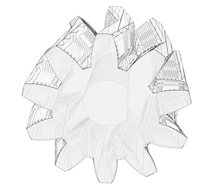

Step 2: Add Pinion to Motor

File or dremel a small flat spot on the shaft of the motor, about 2.5mm wide. This will force the pinion gear to be driven by the shaft.
Then, push the pinion gear onto the shaft, being sure to align the flat on the shaft with the flattened part of the pinion hole. There may be some resistance, be careful to not damage the motor or break the shaft. If the pinion will not fit, you may need to file a larger flat on the motor shaft.
Repeat step with the other motor and pinion gear.
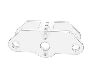
Step 3: Mount Motor to Gearbox


For this step you will need two M3x5 bolts, the motor and pinion from the previous step, the printed gearbox, and a M2.5 hex key.
Insert motor in the hole on the gearbox. Align mounting holes in motor with those on the gearbox, and screw bolts into the assembly. You do not need to tighten bolts extremely tight, doing so could crack the plastic. As long as they are fairly snug they should hold in place. Loctite can be added to reduce the possibility of bolts vibrating out.
Repeat step with other motor and gearbox.
Step 4: Making the Wheels


For this step you will need four rubber wristbands, and 4 printed wheels.
Wrap wrist bands around the slot on the wheels. Repeat for each wheel.
Step 5: Build Gearboxes


For this step you will need the gearbox assembly, the 1/4" shafts the bushings, and the wheels from the last step.
First, insert the bushings on the inside of each of the four holes in the gearbox.
Next, place one wheel so it is wedged inside the bushings and the gears mesh.
Now, drive a 1/4" shaft through the bushing and wheel so is inserted fully inside the gearbox. The shaft should be held in place securely by friction from the hole in the wheel. If it is too loose, glue can be used to secure it, but I would recommend not doing this, as I cannot see a way to add glue without getting it in the bushings.
If the bushings or shaft do not fit into their plastic fitting, use a file to enlarge the hole, or try reprinting with a modified hole size.
Repeat this step for the remaining gearbox.
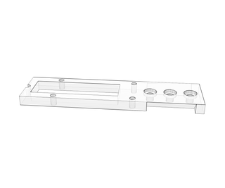
Step 6: Build Cross Brace


This part is used to connect the two gearboxes, so that they form a chassis. My printer cannot print a brace wide enough, so I broke it into three pieces, which can be bolted together. For this step the M4 tap, 5 M4x10 bolts, and a M3 hex key are needed.
Use the tap to thread each of the holes highlighted in red on the photo above. Run the tap through until the tip comes out the other side, and then thread the tap back out. If you continually thread it, the holes will be cut away and will be too loose for the bolts to be held in place. Next, bolt the parts together as shown in the pictures. Again, do not over-tighten the bolts, the plastic will strip. Once you start to feel some resistance and the surfaces are snug together, the bolts are tight enough. Super glue can be added to secure the bolts in place more reliably.
Step 7: Put It All Together


For this step you need the remaining parts, six M4x10 bolts, the cross brace, both gearboxes, the M3 hex key, and the M4 tap.
First, thread all of the holes on the top of each gearbox with the tap. Try to only thread the tap about 5mm into the plastic, any more and you will just eat away material from the hole.
Now, place the cross brace on top of the gearboxes, and put six(three per side) bolts into the threaded holes to secure each gearbox to the brace. As before, do not tighten the bolts too much, as it will strip out the threads. Super glue can be added to secure the bolts in place.
Now all you need to do is add your own electronics, and you have a running robot/RC car. I will do another Instructable in the near future about my own Raspberry Pi controlled robot using this chassis if there is sufficient interest.
Note: The extra holes that are on the top brace and are unused are for mounting hardware onto the chassis. They can be tapped, and the same M4 bolts can be used to bolt things to the brace.
Let me know if you have any questions about the build or materials.
-Kevin Marshall
Enjoy!

Participated in the
Design Now: 3D Design Contest 2016


![Tim's Mechanical Spider Leg [LU9685-20CU]](https://content.instructables.com/FFB/5R4I/LVKZ6G6R/FFB5R4ILVKZ6G6R.png?auto=webp&crop=1.2%3A1&frame=1&width=306)


