

Introduction: Simple Transistor Tester


Hello hello ladies and gentlemen. like many of you I love to experiment with electronics. I love prototyping on a bread board as well as salvaging parts from pre - existing circuits. And like most people I tend to be forgetful and a trifle disorganized. This often leads to me having a small pile of discreet components on my work bench. The main component being transistors.
I made this simple circuit as a way to remedy that issues as well as a way to test and identify the pin out of most transistors.
Step 1: The Materials


The materials you will need for this project are:
-A CR2032 battery holder
-2 LEDs
-4 1k resistors
-8 breakable female pin headers
-A switch
-A bit of perf board
Step 2: The Tools


The tools you will need are:
-A set of wire clippers
-A sharp knife
-A bit of routing wire
-A pen
-Labels
-A soldering iron
-Some solder
Step 3: The Circuit

The circuit is designed to be able to sort between both NPN and PNP transistors. In both the EBC and BCE configurations. (I am no computer please excuse the circuit. it is Cain Aided Design)
Step 4: Preparing the Board


I accomplished this by using the bw
attery clip as the thickest part of the circuit and scoring the board with the knife. All before snapping the board along the score using the table for suport.
Step 5: Adding Power


Attach the battery clip to the end of the board and attach the switch near the positive termanal. Join the two together and attach the center pin of the switch with some routing wire for a path for power.
Step 6: Adding the Sockets


place the two rows of female pin headers a small distance from the battery make sure to maintain ample distance from the battery to accommodate the other components. While maintaining ample space for the labels to be added later. Note it can be very troublesome seating the headers at first but once the first pin is joined the rest are a snap.
Step 7: Attach the LEDs and Resistors


place the resistors and LEDs according to the schmatic. A resistor on each base. One LED goes to the collector of the NPN via the cathode. And one LED goes to the PNPs emitter via the anode. try to keep the LEDs in line and do not forget the resistor on the positive termanal of the LED. (I was reminded of this heavily by the community and my peers~)
Step 8: Finish Routing


Finish routing by connecting collector of the PNP to positive. Connect both of the PNP's emitters. Connect both of the NPN's emitters together and connect that to ground. Connect the resistor and the cathode of the LED comming from the PNP transistor to ground.
Step 9: Add the Labels
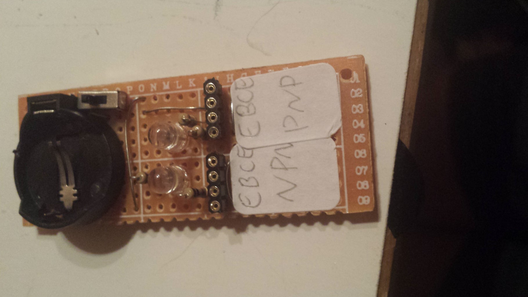
Create the lables and clearly mark EBCE closes to the corresponding point and mark which transistor the port is testing.
Step 10: Finaly Add the Battery and Test~


Place the battery in the clip according to polarity. take your sample transistor and hold it in the headers. depending on your transistors gain you could end up triggering both the NPN and the PNP side. In this case the brightest response will indicate the proper type and orientation. Any responses on how to remedy this would be greatly appreciated. This tester can be used on most BPJ transistors though I have not tried and form of FET.
Thank you and have a pleasant day.

![Tim's Mechanical Spider Leg [LU9685-20CU]](https://content.instructables.com/FFB/5R4I/LVKZ6G6R/FFB5R4ILVKZ6G6R.png?auto=webp&crop=1.2%3A1&frame=1&width=306)


