

Introduction: Solar Based Power Supply for Arduino
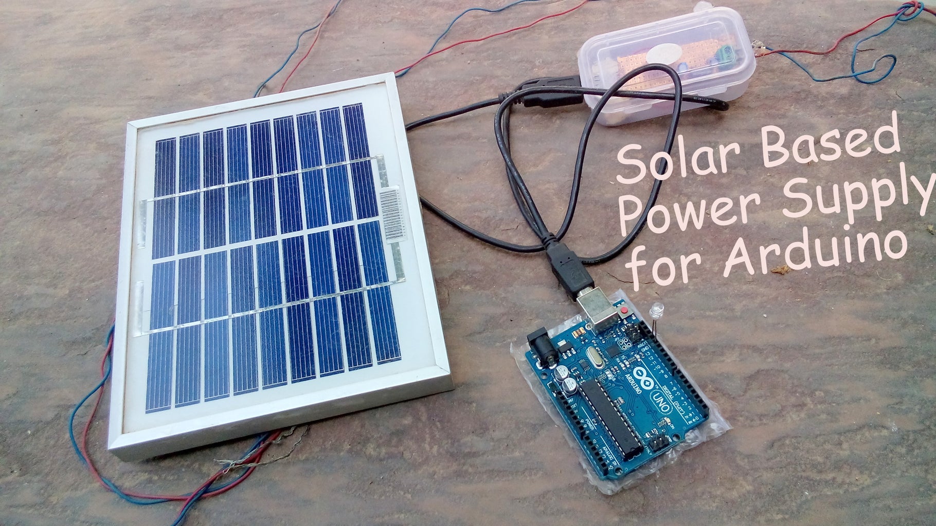


Sometime we have to face a power cut in our home which is a great trouble when we are doing some projects or tinkering with Arduino Boards or similar. Although we can use Power Banks or Laptops or any thing which uses Battery inside. But i think they too need a power to charge themself. What if we can get a enough voltage to power a board say arduino or similar microcontroller. We can use the power of sun to power Arduino. Arduino is compatible with approximate voltage range of 5-12v because Arduino has Onboard Voltage regulator. So here I took 5v voltage regulator or you can use DC-DC buck Converter to get the desirable range. Hence this power supply is not only for arduino but also for various purposes so Lets Built one our own.!
Lets get started!
Step 1: Ingredients You Need


1. Solar panel (any)
2. Zero PCB
3. PCB terminals
4. USB slot
5. Capacitors-10microF*2
6. 7805 Voltage Regulator (You can use Dc-Dc buck Converter)
7. Connection wires
Also Tools you will need :
*Soldering Iron
*Dremel tools
*Glue gun
*Cutter
Step 2: Preparing Circuit and Solar Panel


In Solar panel, at the back side there are two terminal that is one positive and second is negative. We will going to add a terminal at the back side of panel.
Just solder a diode at the positive terminal at the panel (You can also solder the diode in PCB)and then to the PCB terminal. Also connect the negative of panel to the second PCB terminal pin. We now just need to insert the wires and tighten the screw. Panel is ready to use!
It uses a very common and simple circuit in order to step down the solar panel to around 5.0v. This voltage is neccesary to power on the Arduino Board.
If you want to know more about voltage regulator IC then reffer to this link
Connect the circuit according to schematic.
Step 3: Prepare Case With USB Slot!


I use simple plastic casing laying around in my garage.
Just trim off a slot equal to USB and also two holes opposite to USB slot for input terminal from Solar panel.
Be careful while trimming off the slot.
If necessary file it. Insert the USB into place as shown.
Solder the wire to the USB pins that is outer pins. Middle pins are for the Data connections we need not require to connect anything with them.
Solder the Circuit as per the schematic. Connect the USB to the Circuit as shown. Now we are ready to install them into case.
Step 4: Assemble Everything


Time to Assemble Everything and Put it in a Case .Insert the USB into case properly and glue it.
Trim/cut off the un-neccesary PCB such that it can Fit into our Plastic Case. If needed Add support to USB with the help of piece of paper as i did in pictures. That Green terminal is used to connect to Solar Panel. Glue them all and finally you are done. Connect the wires as long as you want . Plug USB cable into slot ans other into Arduino Board (any).
Step 5: Enjoy Unlimited Power Supply or As a Back Up Supply!


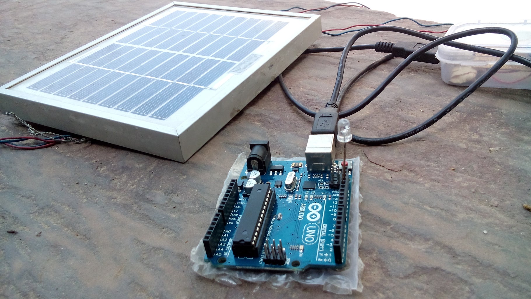
Here we are done with the power sulppy for arduino board for Various microcontroller. Since Arduino has On board voltage regulator which can handel 5-12v easily. I took 5v regulator because this operating voltage is been used in many kinds including phone charging so it a multitasking voltage range.
Hope you liked it.
Please vote for the project and share if you think it was awesome.
Don't forget to follow for more cool projects!!
Fell free to have any query.
Hope you liked my instructable.
***If you liked my project please CLICK Vote! ^ Above ^ ***
Thanks.

Participated in the
Invention Challenge 2017

Participated in the
Before and After Contest 2017

Participated in the
Power Supply Contest


