

Introduction: Speccy-fi Your Pi


In this Instructable, I'll show you how to breathe new life into a ZX Spectrum using a Raspberry Pi. We'll keep that iconic keyboard working with your Pi and I'll give you an easy-to-build inner housing to neatly hold everything inside. Spectrum and Spectrum+, Pi A+ and Pi B are covered, so whichever combination you have, this tutorial is for you.
Before we begin, have a look at the recommended parts below; I've suggested Pi-with-Speccy combinations so you don't have to desolder anything from your Pi to make it all fit together!
Have fun building.
Parts you will need:
- ZX Spectrum or Spectrum+
- Raspberry Pi (recommended model A+ for Spectrum or 2B for Spectrum+)
- Betron 4 port USB hub
- Flexible (with wire) HDMI to VGA adapter (I recommend an official Raspberry Pi one)
- Arduino Leonardo or LeoStick with the Arduino IDE
- Raspberry Pi WiFi dongle
- USB to micro USB cable
- Audio splitter
- Resistors
- 10K (x5)
- Wire
- Perf (prototyping) boards
- 8 x 2 holes (x1)
- 6 x 6 holes (x1)
- Female headers (optional)
- Heat shrink tubing (optional)
- 0.3-0.5mm aluminium sheet (A4 minimum)
Tools you will need:
- Soldering iron and solder
- De-soldering pen
- Scissors
- Snipping tool
- Phillips screwdriver
- Pliers and wire cutters
- Fine flat head screwdriver or knife
- Hot glue gun
- Printer (inkjet)
Acknowledgements:
- Thanks to Grace Ncube for your Raspberry Pi config video.
- Thanks also to Tero Heikkinen for your insights into Spectrum / Spectrum + keyboard membrane differences.
Step 1: Preparing Your Parts


Harvesting your Spectrum
The first thing you need to do is take apart your speccy. Be careful here; you need your keyboard membrane working and it will probably be old and brittle. Fear not if you do break it, you can find brand new replacement membranes and connectors on eBay.
Remove the screws from the underside of the Speccy. Then, holding the two halves together, turn the Speccy upright again in the orientation you would type with. Slowly lift the Speccy lid, keeping the top (port edge) down and slightly towards you. That way the membrane ribbons are nice and loose (see the 1st photo above). Pull the ribbons firmly upwards using both hands for each. The top half should now come away. I recommend using masking tape to gently hold the ribbons to the lid (2nd photo above).
The last bit of prep for your Speccy is to remove the motherboard (there are only one or two screws) and then to desolder the ribbon connectors. If you're uncomfortable with desoldering, again eBay has you covered. Just order one 5-pin and one 8-pin connector. If you are comfy removing the connectors, they're very easy to spot on the underside; the connectors are the only horizontal runs of pins (see 3rd and 4th photos). That's it. You should now have an empty case with keyboard (5th photo) and two connectors.
Preparing your Pi
I recommended the model A+ for the ZX82 or the Pi 2 model B for the Speccy+ because you don't have to do any desoldering to fit your Pi into the speccy. Now that you have your Pi, this is a good time to ensure it has your OS of choice installed and that you have run through all the initial setup stuff. You'll need to ensure your Wifi dongle works and that your Pi is configured to allow the HDMI to VGA converter.
To enable the VGA output, on the boot partition of the OS's card, open the config.txt file and find:
# uncomment to force a specific HDMI mode (this will force VGA)
# hdmi_group=1
# hdmi_mode=1
Change this to read:
# uncomment to force a specific HDMI mode (this will force VGA)
hdmi_group=1
hdmi_mode=1
Now save the file. That's your Pi ready!
Note: If you want a top model Pi (2B) in a ZX82, you'll need to remove the Ethernet and double-height USB ports, then solder single-height USB ports back on.
Preparing your HDMI to VGA adapter and USB hub
You're going to need to strip the plastic casings off the VGA head and your USB hub, to git them as small as possible. To open the VGA adapter, place your flat screwdriver of knife into the rim around the VGA port and leaver the outer case backwards. The face-plate should pop off and the outer casing can slide down the wire. Now snap off the plastic surround leaving just the PCB and port, then finally unscrew the bolts at either side to leave just the VGA connector on the end.
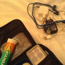
For the USB hub, simply prise off the top and bottom panels of the casing, unscrew the plastic and remove the PCB. I recommend extending the length of the USB cable. To do this, desolder the wires from the contacts and then solder in intermediary wires, keeping to the same colour code. Place lengths of heat shrink tubing around each wire join individually. Then place a larger tubing around all the joins as a group. This will isolate and strengthen the joins. You can see the modified components in the 6th photo.
Step 2: Build the Interfaces


Before we begin, now is a great time to check that all of your modded components from the last section are in working order.
The positioning plate
To make your Pi and components nice and secure, I've made a template you can print off (compatible with Speccy and Speccy+, Pi A+ and 2B) that will securely house your parts and add plenty of strength to the ports. Please find the PDF attached. Print it off and stick it to your sheet aluminium. Drill the circular holes, cut along the solid lines and fold along the dotted lines (1st image). Most flaps should be folded upwards, apart from those shaded grey, which must be folded downwards. The resulting plate should look like the 2nd image above.
Place the plate into the Speccy and screw it down where the original motherboard screws were placed. The components should slot in fairly easily. I recommend securing the VGA adapter head, USB hub and power connector using hot glue. They should now be solidly held for frequent plugging in and unplugging.
The keyboard interface
Lets get your keyboard going! You'll need to make one board per connector. The 8-pin connector (address lines) simply wires the ribbon connector to the Arduino's digital pins. The 5-pin connector wires the data ribbon to the Arduino's analog inputs via 10K ohm pull-up resistors. You can see the two circuits above (3rd image). The 4th image shows you how you can implement the circuits on the perf boards. Note the orientations of the ribbon connectors; the data connector (5-pin) has contacts at the bottom and the 8-pin has contacts at the top. Personally, I added headers to the boards rather than soldering the wires straight on so that they are easy to disconnect or change over if I make a mistake. Make sure you position it all out before you decide on your wire lengths; the ribbon connectors have to be aligned to where the ribbons come out of the lid. When you're happy, connect it all up and hot glue the boards into your lid. Plug your ribbons in gently and tape them down to protect them. You can see this above in the 5th and 6th images. Finally, position your Arduino where there will be room when it gets closed up. Glue it to the lid too and plug your wires in.
The great news is that the software is done for you. I've written an Arduino Leonardo driver sketch for your Leonardo or Leostick. Please find the zip file attached. Download it, add the uncompressed folder to your Arduino sketches folder and the sketch should open. Upload it to your Arduino Leonardo or Leostick.
The sketch will enable your Leonardo to recognise the connections made by the button presses on your Speccy or Speccy+ and output the corresponding keyboard strokes through USB. The top half of your Speccy is now a universal USB keyboard you can plug into anything. Plug it into your Pi or computer and give it a test run.
IMPORTANT: Don't forget about that ever fragile membrane; best to keep the two halves of the case together whenever you type to avoid squishing and cracking the ribbons!


Step 3: The Final Assembly


The easy bit. I'm showing you this one on the ZX82 specifically because it is the harder of the two to get everything in. In the Speccy+, you have bags of room to play with. Plug your WiFi adapter and the Arduino Leonardo or Leostick into the inward-facing USB ports on the hub. Connect the hub, HDMI, audio jack and power extension to the Pi. Check you're happy with everything and ensure everything except the Pi is hot glued as securely as possible. The beauty of this build is that your Pi is completely removable at any time. Finally, close it up, pop the screws back in underneath and off you go.
I hope you enjoyed this build and have great fun with your new, iconic Raspberry Pi. Please let me know how it goes!
Participated in the
Raspberry Pi Contest

![Tim's Mechanical Spider Leg [LU9685-20CU]](https://content.instructables.com/FFB/5R4I/LVKZ6G6R/FFB5R4ILVKZ6G6R.png?auto=webp&crop=1.2%3A1&frame=1&width=306)


