

Introduction: YouTube Subscriber Counter Using an ESP8266 Board


Dear friends welcome to another ESP8266 project Today we are going to build a DIY YouTube subscriber counter with a big LCD display and a 3D printed enclosure. Let’s get started!
In this tutorialwe will be making this: A DIY YouTube subscriber counter. It uses the big I2C display I reviewed a few weeks ago to display the subscriber count with big easy to see from distance numbers. The enclosure of the counter is 3D printed using wood filament. I used two different wood filaments this time and I really love the color combination! In my opinion it looks so cool. I really wanted a YouTube subscriber counter to help me stay motivated! Producing videos requires a great amount of time and effort. When you know that 35.000 people are waiting for a video from you, you work harder and harder to keep all these people satisfied, it gives you a great motive. So, this counter will help me stay focused. Let’s now see how to build this project!
Step 1: Get All the Parts

The project is really simple and easy to build. The parts needed in order to build this project are the following:
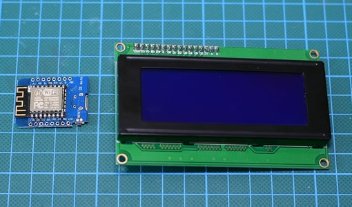
- A Wemos D1 mini board ▶ http://educ8s.tv/part/D1Mini
- A 20x4 LCD display ▶ http://educ8s.tv/part/20x4LCD
- Some wires ▶ http://educ8s.tv/part/Wires
- Power Bank ▶ http://educ8s.tv/part/Powerbank
The cost of the electronics is less than 10$!
If you are going to 3D print the enclosure you are also going to need two rolls of the wood filament. I used FormFutura’s Easy Wood Birch and Coconut filaments.
Coconut filament ▶ http://bit.ly/WoodFilamentCoconut
Birch filament ▶ http://bit.ly/WoodFilamentBirch
For the enclosure, we need about 100gr of material, so it will cost us around 5$.So the total cost of the project is around 15$.
Step 2: The Wemos D1 Mini Board

The Wemos D1 mini is fantastic new board which costs around $5!
The board is very small. It uses the ESP8266 EX chip which can operate at a frequency up to 160MHz. It has a lot of memory, 64Kb of instruction RAM, 96Kb of data RAM and 4MBs of flash memory to store your programs. It offers WiFi connectivity, Over the Air updates and much more. The D1 mini board offers 11 GPIO pins and one analog input. Despite its small size many shields are being developed for this board which I think is great, since this way we can easily build great Internet of Things projects! Of course we can program this board using the Arduino IDE.
The board despite its small size it outperforms all the other Arduino compatible boards in performance. I have performed a comparison between the ESP8266 and Arduino, you can check the video I have attached in this step. This board is 17 times faster than an Arduino Uno! It also outperforms the fastest Arduino board, the Arduino Due. All that, with a cost of less than $6! Impressive.
Get it here ▶ http://educ8s.tv/part/D1Mini
Step 3: The 20x4 Character LCD Display

I discovered this display some time ago on Banggood.com. It drew my attention because it inexpensive, it costs around 7$, it is big, and it uses the I2C interface. Since it uses the I2C interface it is extremely easy to use with Arduino. We only need to connect two wires. I needed a big, easy to connect display for prototyping some projects and the only display that was using the I2C interface was this tiny OLED display. Now we have a big I2C display to use in our projects! Great!
As you can see, the display is really big. It can display 20 characters per line, and it has 4 lines. It cannot draw graphics, just characters. At the back we can find a small black board soldered on the display. On the black board there is a trimpot which controls the contrast of the LCD.
Get it here ▶ http://educ8s.tv/part/20x4LCD
Step 4: Build the Prototype Circuit


The connection couldn’t be easier.
Connecting the LCD Display
- Vcc of the display goes to the 5V output of the Wemos D1 mini
- GND of the display goes to the Wemos GND
- SDA pin of the display goes to D2 pin of the Wemos Board
- SCL pin of the display goes to D1 pin of the Wemos Board
That’s it! Now if we power up the project we can see that after a few seconds the board is connected to the WiFi network and on the screen the number of the Subscribers of this channel is displayed with big numbers. The project works as expected so we can move on.
Step 5: 3D Print the Enclosure


The next step is to 3D print the enclosure. I designed this enclosure using Fusion 360 free software.
I tried a lot of different 3d design software but Fusion 360 became my favorite for the following reasons.
- It is very powerful and it is free
- It is relatively easy to use
- There are a lot of tutorials online on how to use this software
I took me around an hour to design this enclosure and have in mind that I am very new to 3D design and 3D printing. I have uploaded the design files to Thingiverse and can download them for free.
I used Formfutura’s EasyWood Coconut filament for the two parts, and Birch filament for the front part.
Get it here ▶ https://www.thingiverse.com/thing:2338562
Step 6: Finish the 3D Print


It was an easy and quick print. It took me around 5 hours to print all the parts using my Wanhao i3 3d printer. but The result was fantastic!
After the parts were printed, I sanded them with fine sand paper and then I applied wood varnish to them. I used different wood varnish for each color and I applied it using a small piece of cloth.
Next, I let the varnish to dry for 24 hours and the end result is great!
Step 7: Connecting Everything Together


After thevarnish was dry it was time to put the electronics inside the enclosure.
I glued the front piece in place and then I placed the display to its exact position.
I used some hot glue to keep the display in place as well. Then I soldered some female wires to the Wemos D1 mini pins we are using, and then I connected them to the display. I tested the project to see that everything is working fine, and then I used hot glue to glue the board in place. The last step was to glue the back cover of the enclosure!
Our project is ready and it looks so cool! In my opinion it does not look plastic like most 3D printed objects look! I really love how it turned out. Let’s now see the code of the project.
Step 8: The Code of the Project


The project retrieves the number of the subscribers of a given YouTube channel using the YouTube API. We send a request to a google server and the server replies with a JSON file with the number of subscribers. In order to use the YouTube API we need to have an API Key.
Let’s do that first. So, we have log in to our Google Account and visit the developer console. (https://console.developers.google.com) We click to create a new project, we give it a name and we press create. Then with the new project selected we enable the YouTube Data API. The last step is create Credentials. We press the Credentials key and then from the window that appears we select to create a new API key. We press close and we are done. For more details, watch the video attached to the first step.
Let’s now take a quick look at the code of the project. First of all we have to download some libraries. We need a version of the LiquidCrystal_I2C library which works with the ESP8266 chip. We also need the excellent ArduinoJSON library.
- Arduino JSON: https://github.com/bblanchon/ArduinoJson
- Display Library: https://github.com/esp8266/Basic/tree/master/libr...
Next we have to define some variables. We set the ssid and the password for the WiFi connection. We also need to enter the API key we created in the appropriate variable. Lastly we need to enter the channelID of the YouTube channel we want to check the subscriber count.
<p>const char* ssid     = "SSID";       // SSID of local network<br>const char* password = "PASSWORD";   // Password on network
String apiKey = "YOURAPIKEY";       //API KEY
String channelId = "UCxqx59koIGfGRRGeEm5qzjQ";   // YouTube channel id</p>
The code is relatively simple. At first we initialize the display and we create some custom characters for the display. We need these characters in order to produce big digits. Don’t forget, the display we are using is character LCD display, it cannot display graphics. It can just display 4 lines of text. In order to create big numbers, we use two lines of text and some custom characters!
<p>void setup()  <br>{
  Serial.begin(9600);
  int cursorPosition=0;</p><p>  lcd.begin(20,4);
  lcd.setCursor(0,0);
  lcd.print("Connecting ....");</p><p>  createCustomChars();

  WiFi.begin(ssid, password);

  while (WiFi.status() != WL_CONNECTED) {
    delay(500);
    lcd.setCursor(cursorPosition,1);
    lcd.print(".");
    cursorPosition++;
  }</p>
Then we connect to the WiFi and we get the subscribers every minute. In order to get the subscriber count, we send a request to a google server, and we parse the JSON fine it responds using the ArduinoJSON library. We save the subscriber count into a variable. In the loop function we check if there is a change in the subscriber count, we clear the display and we print the new number.
<p>void loop() <br>{
  int length;
  String subscribersString = String(getSubscribers());
  if(subscribers != subscribersBefore)
  {
    lcd.clear();
    length = subscribersString.length();
    printSubscribers(length,subscribersString);
    subscribersBefore = subscribers;
  }
  delay(60000);
}</p>
As always you can find the code of the project attached in this Instructable. Since I update the code from time to time, for the latest version of the code please visit the project's website: http://educ8s.tv/diy-youtube-subscriber-counter/
Attachments

Step 9: Final Result
As a final thought, I really love this project. It was really easy to build and inexpensive. Of course there is room for improvements. We can add a battery inside the enclosure or even sound. I am thinking about adding an 18650 lithium battery along with the wemos battery shield. I didn’t do it in this project because I need to test the Wemos Battery shield some more. This small shield can charge and protect Lithium Batteries so it provides an easy way to add rechargeable batteries to our projects.
I would love to hear your opinion about this project. Do you like how it looks and can you think of any improvements to this project? Please post your comments in the comments section below.

Participated in the
Invention Challenge 2017


