

Introduction: Fit Tests


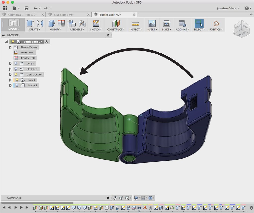
With a simple project completed, it's time to learn to make objects that are more complex. This will mean working with moving parts and assemblies. In the Bottle Lock lesson, we're going to make a model that has two halves with a built-in hinge that will allow the two parts to move in a clamping action.

Before we go too far in designing all the features we'll need to combine the separate parts of a complex model (tabs, slots, posts, holes, etc.), we need to print a test object so we can see how precise we have to as we are designing the model.
Anytime you 3D print an object that's designed to interface with another object (whether printed, manufactured, or fabricated by another method), there is an important factor to consider: Tolerance.
Think of the tolerance as the allowable limit of variation on the dimensions of parts that have to connect to other parts. For example, if your tolerance is 0.00, then you would design a 5mm hole to fit a 5mm peg- with a desktop FDM printer, this won't work because the tolerance is too high. The peg will have to be forced into the hole and will probably break the part.
A tolerance of 0.50 would mean that a 5mm hole would fit with a 4.5mm peg. The slightly smaller peg will allow it to move freely inside of the hole. This would be considered a "low tolerance" in the world of 3D printed parts.
Tolerance is a very important factor in 3D printing because (like any kind of manufacturing or fabricating), nothing is ever created perfectly. There are always variations on the actual dimensions of printed objects, and you need a good understanding of the limits of the particular technology you're using if you want to be able to anticipate your results.
- A higher tolerance (0.00mm - 0.05mm) can make for a tight fit, but depending on the performance of the 3D printer and slicing software, a tolerance that's too high will mean that parts can't be fit together at all.
- A lower tolerance (0.15mm+) will ensure that parts can fit together, but if the tolerance is too low, the parts will fit loosely, and assemblies will be imprecise.
What to do!? How do you decide what dimensions to use to make sure your parts fit together properly? It's actually really easy- all you have to do is print a copy of John Edmark's model from his Objet 3D Printer Fit Tests instructable and try it out on your printer with your slicer.
Step 1: What You'll Need
FIT TEST FILES
The STL file attached here is ready to print- you can just bring it into your slicer as-is and print it out. The F3D file attached here is a Fusion file that you can open and edit yourself.
FUSION 360 INSTALLATION FOR MAC / PC WITH 64 BIT PROCESSOR

- Follow the link to download Fusion (don't use the App Store on Mac).
- Enter your email and download the free trial.
- Install and setup a free Autodesk ID account.
- When you open Fusion, select the Trial Counter in the upper toolbar.
- In the next dialog box, select "Register for Free Use".
- Sign up as a Student or Educator (Free) or Sign up as a Start-Up or Enthusiast (Free).
- Select the "I accept Terms and Conditions" checkbox and click Submit.
FUSION 360 BROWSER APP
If you don't have a Mac or PC with a 64 bit processor, Fusion won't work on your machine. A browser-only version of the app is currently in beta, follow this link to sign up and use it for free:
SIMPLIFY 3D OR CURA
For the remaining lessons I'll be using Simplify 3D because it has superior support structures. It costs $150, but the results are second to none. Here's a link to download page:
If you want to use free software, Cura is a good alternative:


Step 2: Slice and Print
John Edmark’s Objet 3D Printer Fit Tests instructable is a great way to test tolerances for your design. It has a Fusion model with a row of male gauges that step down in width by .002” (.05mm) and a female box that fits over them. He has 3 different models that correspond to the quality settings on the Objet DLP printer, but any one of these will do for our purposes.
Slicing the Fit Tests Model
I download the fusion model from the instructable and upload it to Fusion. The way the parts are laid out makes the model too big for the Dremel build platform, so I move them so they’re below the row of gauges.
The model is made up of Bodies under the main model, not Components of their own. Making bodies into components of their own makes models easier to keep organized, and creates new functionality (such as joints, which we'll cover in the next lesson).
To turn bodies into components, click the drop down arrow next to Bodies in the Browser to show all the bodies in the model. Right click on any body, then select "Create Components from Bodies"in the popup menu. You will now have a new independent component in the Browser.
To move objects in Fusion, just click on the components in the browser, then right-click and select Move in the popup menu.


To send the model to my slicer, I select the component at the top of the browser, right-click, and select “Save as STL”. This will give me a single STL file with all the parts placed where I want them.
For this print, I'm going to use Simplify 3D because it has better support structures than Print Studio for FDM printing. More on that later.
Step 3: SIMPLIFY 3D
1.IMPORT: In Simplify 3D, click the Import button on the left-side panel, and select the Fit Tests STL file in the browser.

2. ROTATE: Fusion defaults to Y being the up axis (this is typical for 3D modeling software for some reason), so you're going to have to rotate the model so it’s placed on the printer bed in a logical way. Double-click on the model and Position / Scaling / Rotation controls come up. Rotating the Y and Z axes by 90º gives you the orientation you want. You can also go to Edit > Place Surface on Bed and click the surface you want on the bed.

3. CENTER: Instead of using the Change Position values to move my model around, just click Center and Arrange in the pane on the left. This automatically places the model centered on the build platform.

4. CONFIGURATION ASSISTANT: On Mac, this option can be found under Help > Configuration Assistant. This is a setup wizard that will apply the necessary settings to the program, giving you useful default settings for printing. It will also export the tool paths (instructions the 3D printer can understand) in whatever format your 3D printer can read.


5. EDIT PROCESS SETTINGS: Click the Edit Process Settings button in the panel on the left to open the settings panel. The default settings are a good place to start, but as you're troubleshooting, this is where you'll be making the adjustments to get better results.

6. PREPARE TO PRINT: Click Prepare to Print, and Simplify 3D gives you a tool-path with supports using its default settings. You can move the Preview sliders to see how the print head is going to build the model. Click Save Toolpaths to Disk, save the .g3drem file to an SD card and that’s it! You're ready to start printing.

Step 4: Test Tolerances

Now that we have a printed Fit Test model, we can check the tolerances and find out which ones work best for model features.
I find that the .006" (.15mm) tolerance gives me a snug fit while still leaving wiggle-room to remove the piece. .2mm gives me an easy in-and-out fit. Anything bigger than .2mm feels very loose, and anything smaller than .15mm makes for a more or less permanent press-fit.
This is a great piece to keep around while you're designing. It will help you make decisions about what tolerances are appropriate for interlocking parts.
{
    "id": "quiz-1",
    "question": "Do tolerances matter for parts that don't connect to aything else?",
    "answers": [
        {
            "title": "No",
            "correct": true
        },
        {
            "title": "Yes",
            "correct": false
        }
    ],
    "correctNotice": "You got it! Why bother finguring out tolerances if there's nothing to connect the part to?",
    "incorrectNotice": "Nope! Why bother finguring out tolerances if there's nothing to connect the part to?"
}
Step 5: Homework

Your homework this week is to print out your own Fit Test model. Keep it handy for the rest of your life and let it help you make good decisions about design tolerances.


