

Introduction: Generator 100% Stator Earth Fault Calibration


100% stator earth fault protection is provided by injecting a 20Hz voltage signal into the secondary of generator neutral grounding transformer through a band pass filter. The band-pass filter passes only 20Hz signal and rejects out-of-band singles.
The main advantage of this protection is 100% protection of the stator windings for earth faults - including when the machine of off-line (provided 20Hz signal is present)
Supplies

Only equipment required is Decade resistance box and some connecting leads. It is always advantageous to keep protection relay user manual handy during calibration.
Step 1: Connections
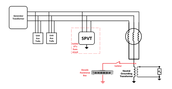
- During calibration procedure, only single earthing path should be present in the circuit. All other parallel paths must be isolated temporarily like voltage transformers at generator terminals.
- Connect Decade resistance box across neutral grounding transformer primary. Make sure to insert isolator in series to disconnect the decade box since resistance values will change if it is in service for long duration due to heating at lower resistance values. Change in decade box resistance will introduce error in calibration. We can also add fix value resistance of 500 ohms or 1kOhms, 1Amp after isolator to control heating at lower resistance values.
Step 2: Procedure
The procedure is based on MICOM P345 relays philosophy. Generally the process will remain the same. Compensation values during calibration may vary depending on make and model of the protection relays. For detail theory and calculations, please refer user manual of respective relay.
Note down all protection settings related to 100% Stator earth fault and also related measurements.
There are three stages of calibration
- Setting angle and series resistance compensation
- Fine tuning angle and series resistance compensation at alarm and trip setting values
- Setting parallel G compensation with voltage transformer in-line
- Checking operation of relays at various resistance values
Stage 1 :
- Isolate all parallel paths like voltage transformers.
- Keep isolator in open condition.
- Reset 64S Angle, 64S R Series & 64S Parallel G compensations to 0.
- With no-fault condition, check for '64S Angle' in measurements. It should be +90 deg. If it's not, adjust the value using '64S angle compensation' to read +90 deg.
- Now short start point to ground and check '64S R Primary' in measurement. It should be 0 and if not, adjust '64S Series R' to make measurement to read 0 ohm resistance. Remove the short at star point.
Stage 2 :
- Set resistance equal to trip value in decade box and close the isolator
- Check for measurement of '64S R Primary'. Adjust '64S Series R' compensation for minor corrections or '64S Angle' compensation for major corrections.
- Repeat same process for alarm value
Stage 3 :
- Now take voltage transformers and other parallel circuits, removed into first stage, into service.
- Note down '64S R Primary' value in measurement.
- For applying '64S Parallel G' compensation, calculate reciprocal of value measured in step above.
- Set calculated value into '64S Parallel G' compensation in settings.
Stage 4 :
- Insert various resistance values into circuit and check for correctness of the measurement.
- if values are not matching, whole process need to be carried out again.
Step 3: Final Thoughts
The procedure mentioned above may look easy to execute. To achieve trip and alarm value by adjusting compensation, it takes much time and lot of patience.
Any correction / suggestion / query is always welcome.
Sample test format is attached HERE for ready reference. Feel free to use / modify the same.
This information can also be accessed HERE.


