Introduction: How to Make a Battery Tester and Voltmeter
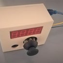
The video above demonstrates how the battery tester is used, by simply tapping both ends of the battery with the probes. The 7 segment display displays the voltage of the battery under a load condition. The joystick sets the threshold voltage, below which the battery is considered to be out of charge. If the battery is out of charge, the piezoelectric buzzer alerts the user. The voltage level of the battery indicates the amount of charge remaining in the battery. For a typical rechargeable AA and AAA battery, the normal voltage is around 1.2 volts. For non-rechargeable ones, it is 1.5 volts.
This battery tester is very useful for me. It helps me to quickly and reliably determine which battery is out of charge. In some of my projects, I use as many as six AA batteries. Even if only one of the six is flat, then the project has unstable power supply. This battery tester has helped me diagnose circuits.
Supplies
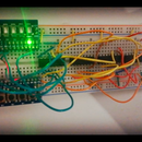
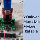
Most of the components are soldered onto the PCB, so you can see most of them in the photos above. I have attached a complete list of supplies as a PDF below.
Attachments
Step 1: Make the PCB and 3D Prints
This project shares the same PCB design and 3D prints as: https://www.instructables.com/How-to-Display-and-Set-Numbers-With-7-Segment-Disp/, which uses the PCB for a timer. The two projects are related and demonstrates the versatility and adaptability of the design. The Arduino code for the voltmeter and battery tester is different to the timer, and is attached under Step 4.
There are some differences between the projects. For the battery tester, solder a 330Ω resistor for R7; for a voltmeter solder a very large resistor (e.g. 1MΩ) for R7. A good voltmeter does not draw much current from the circuit being tested, so its resistor (R7) needs to be large. By drawing a minuscule current, the voltmeter does not interfere with the circuit's performance. When testing a battery, you want to test it at certain load current. A typical rechargeable AA battery has 1.2V, so the current equals 1.2V / 330Ω = 0.0036A. Testing the battery at 3.6mA is more accurate than testing at some nano-amperes of current.
For both the voltmeter and battery tester, solder a wire to TP1 and a separate wire to pin 1 of P3 (which is GND) (see the blue and yellow wires in the photo above). The wire will be used to make contact with the two terminals of the battery or where the voltage is measured.
Step 2: 3D Print the Probes
You also need to 3D print the two probes. The STL file is attached below. The 3D print has 1 mm overhang for the grooves which may cause imperfections during printing. Slide the metallic split pin through the hole in the 3D prints.
Attachments
Step 3: Attach the Probes
After assembling the parts from Step 1 in accordance with https://www.instructables.com/How-to-Display-and-Set-Numbers-With-7-Segment-Disp/:
- Slide heat shrink tubing onto the (yellow and blue) wires
- Solder the (yellow or blue) wire onto the split pin
- Hot glue the split pin to the 3D print. Ensure that it is secure. Apply hot glue to where the split pin enters and exits the hole of the 3D print.
- Use the heat shrink tubing to cover up the solder joint and hot glue, as shown in the photo above.
Step 4: Upload Code
The code is on GitHub: https://github.com/bz36912/voltmeterArduino
The code is explained using in-line comments. On the GitHub, the "Arduino Battery Tester documentation.docx" contains further explanations and diagrams (finite state machine diagram and subsystem breakdown diagrams). I uploaded the code onto the Atmega328-PU using the USB TTL adapter. The adapter is plugged into P2 header on the PCB.
It may be confronting that the code uses multiple CPP and header files, but this file structure improves code modularity and organisation.
Step 5: Multi-purpose PCB
The PCB used in this project is designed to be versatile and adaptable. In this Instructables, the PCB is used for a voltmeter/battery tester. As you have already seen, the PCB can also be used for a timer. In a future Instuctable, I will show how it can be used as a bluetooth remote control for a robot car.
Feel free to add your creativity and post photos in the comments section below.


