

Introduction: How to Use Piezo Buzzer / Beeper With 555 Timer
If you are already using a micro-controller (e.g. Arduino) in your project, this Instructables is not for you, since the micro-controller can replace the 555 timer's function. If you are using an Arduino, check out https://www.instructables.com/How-to-use-a-Buzzer-Arduino-Tutorial/.
This Instructables explores how 555 timers can used with piezo-electric buzzers, so there is no need for software or programming. The frequency or pitch of sound can be changed by adjusting the capacitor and resistor values attached to the 555 timer. Thus, this project offers a very different learning experience to using a micro-controller.
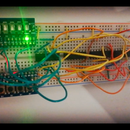
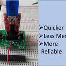
A single tone or frequency of sound can be quite boring. To spice things up, this project's circuit produces a 500 Hz tone for a second then a 1 kHz tone for another second, as can be heard in the video above. In this project, I made a PCB, but you can do the same on a breadboard. The Altium PCB files are on https://github.com/bz36912/PCB/tree/main/Dual_tone_generator.
Supplies

- 3X 555 timers
- 2X piezo buzzers (I got mine from https://www.digikey.com.au/en/products/detail/db-unlimited/TP124005-2/9990670)
- 3X 10 to 100nF capacitors
- 3X capacitor (values depending on the sound frequencies and duration you want, see Step 3)
- 6X resistors (values depending on the sound frequencies and duration you want, see Step 3)
- Breadboard or PCB (see Step 4 to see how you can design the PCB)
- 4.5 to 9 volts DC power source (e.g. batteries)
Tools (if using PCB):
- Soldering iron and solder
- Wire cutter
Step 1: Design the Circuit
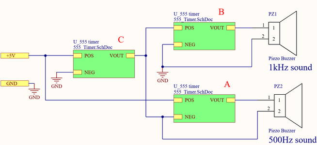
The schematic above shows that the circuit consists of three 555 timer circuits (labelled A, B and C and are represented by the green boxes). More details on the 555 time is in Step 2. Circuit B produces the 1 kHz sound, while A produces the 500 Hz.
Circuit C selects/alternates between Circuit A and B. When C output high (which is +5 volts), B is activated, but A is deactivated (since both its POS and NEG terminals are at +5 volts, meaning the voltage difference between them is 0). When C output low (which is GND or 0 volts), A is activated, but B is deactivated (since bother of its POS and NEG terminals are at 0 volts).
Step 2: Understanding 555 Timer


Click on the pictures above to get a better view. A 555 timer turns a DC input into a square wave output. The schematics on the right is what is inside of each of the green boxes in Step 1's schematic. In the schematics, POS is input and VOUT is the output. The square wave voltage alternates between POS and NEG, as shown in the diagram on the left.
NEG functions like the ground of this 555 timer circuit, but is not necessarily the ground in the larger schematics of Step 1. Step 1 shows that Circuit A's NEG is connected to Circuit C's VOUT, which alternates between ground voltage and +5 volts. Capacitance of C2 can be between 10 and 100nF (I used 100nF). Components labeled TP are just test points, which are optional.
The 555 timer is a popular component, with a lot of supporting resources on the Internet. The datasheet is attached below.
Attachments

Step 3: Choose Sound Frequencies

The equations in the picture above are from the 555 timer datasheet (as attached under Step 2). In my design, I want the charge time to have (as close to) the same duration as discharge time, so I want resistance, Ra, to be as small as possible. I used the minimum recommended value for Ra, which is 1 kΩ.
In my design I want to produce 500 Hz and 1 kHz sounds. Each sound plays for 1 second, so the period of Circuit C is 2 seconds, meaning its frequency is 0.5 Hz. I set Rato 1 kΩ. By substituting Ra and frequency into the fourth equation above, capacitance (C) and Rb are found.
I listed the values of all the capacitors I have, substituted these values into the fourth equation to find the theoretical value for Rb. I picked the capacitor-resistor pair that has the theoretical value for Rb closest to the value of the resistor I have. These calculations can be repetitive, so I used Excel to automate the calculations, a bit like in: https://www.youtube.com/watch?v=qqU2xllewk4&ab_channel=Microsoft365
The values I used for the capacitors and resistors are shown in the picture above.
Step 4: Making the PCB


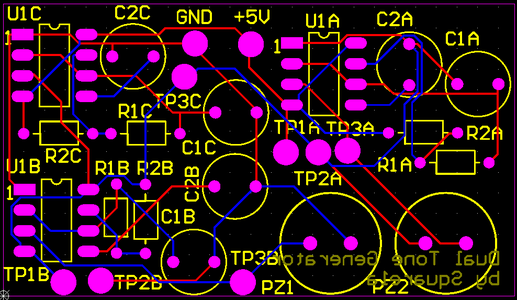
If you are using a breadboard, skip this step. Click on the pictures above to get a better view. The bottom-right screenshot above shows the wiring and layout of my PCB design. The Altium PCB files are on https://github.com/bz36912/PCB/tree/main/Dual_tone_generator.
I ordered my PCB from JLCPCB, but you can also order it from PCBWay or other manufacturers. For JLCPCB, the instructions for uploading the design is on: https://support.jlcpcb.com/article/42-how-to-export-altium-pcb-to-gerber-files
Step 5: Soldering

If you are using a breadboard, skip this step. All components are through-hole technology, so it is quite easier to solder. As a tip, solder the tall components (the buzzers and the electrolytic capacitor) last, after all the shorter components are soldered.
The test points (labeled TP...) remain empty even after all the components are soldered. The test points are for optional circuit testing purposes.
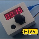
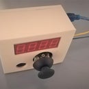
Step 6: Connected It Power

This circuit can be powered by the 5V port on an Arduino, or any other DC voltage source between 4.5 and 9 volts*, with the optimal being 5 volts. Connect the negative power terminal to the hole labeled GND on the PCB, and positive terminal to +5V hole, as shown in the photo above. And listen...
If you have any questions, feel free to leave a comment below.
*the 555 timer is rated for 4.5 to 16 volts (as indicated by the datasheet attached under Step 2), but the capacitors and buzzer used may not be rated for 16 volts. Lower voltage uses less power and is less likely to damage components.

Participated in the
Anything Goes Contest


