Introduction: Linkit One - Strobe Lights
This guides follows on from my previous basic intro into
coding and the Linkit One board (https://www.instructables.com/id/Linkit-One-In-the-beginning/) the focus for this one is to take the single LED and increase the number and then change the code running the board so that the LED's have a strobing effect.
As mentioned this is only one step on from the single LED so should be easy to follow with only a few basic components being added.
There will be additional instructables created that will add to this creating a more advanced set up. These will be small steps so that anyone can follow and create the connections and understand the changes in the code that allow operation to be possible at each stage.
The parts needed for this guide are
- Bread Board (optional – you can make do without it’s just easier if you have one)
- Jumper wires (different colours if possible – makes it easy to see what’s going on)
- Resistors – I will go into values later
- LEDs (9 red)
Step 1: Software
I’m sure that every instructable currently being published
will tell you that its quite complicated and involved to get and set up the software. WELL ITS NOT.
The card itself comes with a 5 step plan that takes you to all the locations you need. The only reason to put extra “personal” instruction in is to pad out the guide.
Here are those 5 steps (straight from the manufacturer.
1. Install the Arduino IDE 1.5.6 or later (I recommend the 1.5.6) Arduino.cc/en/main/software
2. Register on MediaTek Labs – labs.mediatek.com/register
3. Download Linkit Developer’s Guide – labs.mediatek.com/Linkitguide
4. Install Linkit SDK for Arduino – labs.mediatek.com/linkitsdk
5. Select the Linkit One board (from Tools / Boards in the Arduino application)
The MediaTek web site also has videos for all steps required.
Step 2: Resistors
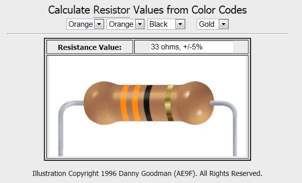
This project uses 33 ohm resistors.
If you don’t know how to work out the ratting for any resistors that you have then – for those that had old fashioned teachers like myself, there is an inappropriate mnemonic, or more correctly there is a website that has a very useful tool (see link below)
http://www.dannyg.com/examples/res2/resistor.htm

Step 3: Wiring Up the Board
Wiring up the board could not be simpler – use the photos as a guide
Looking at the board from the top with the micro USB connector up – you will be wiring the LEDs and resistors to the board pins D4 to D12.
The order is from the D# pin to the green jumper to the end of the resistor to the anode of the LED.
The part of the LED called the Anvil (cathode pin) connects to the GRND pin on the board – in the image see the salmon coloured jumpers which run just above the green ones and connect to a long salmon jumper at the end
Step 4: Code for the Board
The code below is very basic with no apologies you will be able
to find similar examples and are not attributable to any one person – this will be adapted in the next instructable to develop it further the mods will be mine but all are free to use them, after all programming is just the reuse of various different codes in various orders to get a required response.
You should just be able to copy this code into the Aduino application and upload to your board
Start copy after this point:
byte ledPin[] = {4,5,6,7,8,9,10,11,12};
int ledDelay(65);
int direction=1;
int currentLED = 0;
unsigned long changeTime;
void setup(){
for (int x=0; x<9; x++){
pinMode(ledPin[x], OUTPUT);}
changeTime = millis();
}
void loop(){
if ((millis()-changeTime)>ledDelay){
changeLED();
changeTime=millis();
}
}
void changeLED(){
for (int x=0; x<9; x++){
digitalWrite(ledPin[x],LOW);
}
digitalWrite(ledPin[currentLED], HIGH);
currentLED += direction;
if (currentLED ==8){direction = -1;}
if (currentLED ==0){direction = 1;}
}
Stop copy before this point
I have uploaded a very small video – nothing special – just demonstrates the strobing LEDs
Step 5: Resources
- Instrucatle Guide 1 : https://www.instructables.com/id/Linkit-One-In-the-beginning/

Participated in the
Epilog Contest VII

Participated in the
Make It Glow! Contest


![Tim's Mechanical Spider Leg [LU9685-20CU]](https://content.instructables.com/FFB/5R4I/LVKZ6G6R/FFB5R4ILVKZ6G6R.png?auto=webp&crop=1.2%3A1&frame=1&width=306)


