Introduction: Measuring the Refractive Index of Liquid at a Defined Wavelength
Theories behind the sensor
The refractive index of a liquid is an indirect measure of its dielectric constant and composition. For a pure substance, the refractive index is a tabulated physico-chemical parameter. This technique can therefore be used to identify a pure product. For formulations, measuring the index allows the concentration of a species to be quantified, for example the amount of sugar.
The refractive index is measured with a refractometer, which actually operates by measuring the limiting angle of refraction [Фl]. This angle indicates the point at which a light beam incident on a translucent surface of index [n] is no longer able to cross the surface, and instead is reflected, leading to a mirror effect in accordance with Snell's law.
 Before the critical angle, where there is no transmitted beam, the incident light beam (Ii) reflects partially (Ir) and transmits partially (It). The reflective power (R), which is the ratio of the reflected energy to the incident energy, is related to the medium's refractive indexes. By measuring the reflected intensity (Ir), the refractive index of the medium being studied (n2 or n1) can be determined.
 Depending on the nature of the interface (1/2), there can be a significant variation in its reflective power (R). The reflective power will gradually increase as the angle of incidence increases, naturally taking the value of 1 when the angle of incidence [Ф] is close to [Фl]. The table below calculates the limiting angle of refraction [Фl] and the reflective power under normal incidence (R90).

Step 1: Components
Our designed diffractometer functions similarly to this raindrop sensor [1]. To analyze liquid samples, a laser beam with a wavelength of 650 nm is directed onto the liquid surface. The reflected beam intensity is measured by a photo detector. A particular shape is required to achieve an incident angle close to 45°:
 The trapezoid shape is used to ensure an incident angle of 45° angle. it has a height of [h] and bases of [4h] on one side and [2h] on the other. To set up the experiment, position the laser and photodetector at half the diagonal. A mirror is placed on the larger base to direct the incident beam onto the surface to be studied on the left and the reflected beam onto the photodetector on the right.

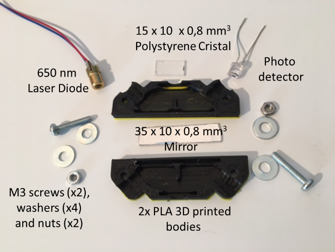
To assemble the equipment, the following items are required:
- 2 M3 screws with a minimum length of 15 mm;
- 2 M3 nuts;
- 4 M3 washers;
- A piece of Cristal polystyrene (CD case) with L = 15, l = 10, and e = 0.8.
- The setup includes a mirror made of Crystal polystyrene coated with an aluminum foil (aluminum foil for food cooking application) dimensions L = 35, l = 10, and thickness e=0.8.
- A red diode laser (650 nm),
- A photodetector,
- And 2 parts that have been printed in PLA using a 3D printer.
The two symmetrical PLA components we design have the following dimensions:

The middle of the trapezoidal cavity, with a depth of 5mm, follows the (h,2h,4h) rule mentioned earlier. The shape is rounded through chamfering. A vertical element with a height of 6.5mm and a thickness of 1mm is used to separate the two compartments, one for the transmitter (laser) and the other for the receiver (photodetector) and then prevent light interfering. The mirror is placed on the larger base while the polystyrene window is on the smaller base. The latter has a housing of 6.5mm diameter to hold the liquid to be measured. The laser and photodetector are housed in cylinders with a 6.5 mm entrance diameter and a 5.5 mm exit diameter. There are two 3.2mm holes for M3 screws, and the component's base has a 1mm thickness.
Step 2: Assembling
The assembly is uncomplicated and can be completed in 4 steps :

1) Two 8mm wide strips are cut from a CD cover made of Cristal polystyrene, a material known for its transparency, rigidity and resistance to solvents. One strip is adjusted to a length of 35mm and covered and glued with food grade aluminium foil to form a mirror. The second strip is adjusted to a length of 15mm and will function as a measurement window;
2) Adjust the mirror in the designated housing, taking care not to damage it. It is recommended to glue this element with cyanoacrylate glue (Superglue) to ensure its fixation. Wait for the glue to dry completely before proceeding with the assembly;
3) Place the laser diode, photodetector, and Crystal polystyrene window in their respective housing without immobilising them with glue. Consistency in replacement of the window is key in this device. The Crystal polystyrene window may require replacement with a new or alternative transparent material depending on varying needs, wear, and the liquids being tested. For the laser, it may be beneficial to measure the refractive index at a wavelength that differs from the 650 nm wavelength detailed in this presentation;
4) The assembly is fastened using two M3 screws, along with corresponding washers and nuts. For ease of disassembly, it is recommended that the simple nuts are replaced with wing nuts.
Attachments
Step 3: Electronics
The electronic enables the reflection to be converted into an electrical signal that can be used to measure the refractive index. A photodiode transforms light into electric current [i]. The output light intensity [iphoto] is determined by the input optical power [Ev] according to a power function [β]. When the photodiode receives illumination, it behaves like an ideal current source whose intensity is connected to the number of photons that arrive on the active surface.
Measuring light intensity is not a simple task. It involves assembling a circuit that links the measured light intensity to the corresponding voltage. A resistor [RPHD] is used to insert a photodiode into reverse mode. The resistor allows the conversion of current produced by the photodiode into a voltage that an operational amplifier can measure.
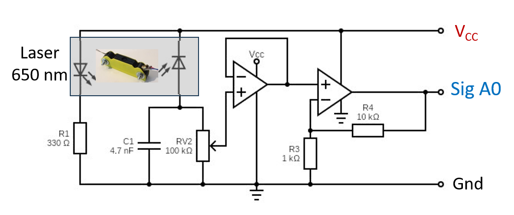
 In practical terms, the photodiode is coupled with a variable resistor [RV2] to adjust the voltage at the positive input of the first op-amp designed in follower mode. The second operational amplifier is employed in non-inverting amplifier mode to amplify the output signal of the first AOP by a gain [G] as determined by (G = 1 + R4/R3). In the given practical example below, the gain is equal to 11 :

The laser operates with the protection of resistor [R1], which limits the current passing through it. The operational amplifier would function properly without the presence of the capacitance [C1 of 4700pF]. However, it is better not to leave an AOP input without a signal if the photodiode is exposed to low light. Hence, capacitance [C1] serves its purpose. On the other hand, the inclusion of resistor [R2] allows for the construction of a low-pass filter with a cut-off frequency of around 500 Hz, thus eliminating the noise that could give us unwanted parasitic detections on the analogue output [Sig A0].
Step 4: References
[1] Gérard Villemin : http://villemin.gerard.free.fr/aGeneral/Transport/Pluie.htm
[2] Refractive index. Info : https://refractiveindex.info/?shelf=organic&book=acetone&page=Rheims
Component parts : Refractive index device, R1 = 330 Ω, RV2 = 100 kΩ, R3= 1 kΩ, R4= 10 kΩ, C1 = 4.7nF, 2 AOP = LM 393
Step 5: Acknowledgment
Thanks to tengamari4615 who pointed out an inconsistency in the schematic


![Tim's Mechanical Spider Leg [LU9685-20CU]](https://content.instructables.com/FFB/5R4I/LVKZ6G6R/FFB5R4ILVKZ6G6R.png?auto=webp&crop=1.2%3A1&frame=1&width=306)


