Introduction: X, Y, Z Joystick ON/OFF
Many applications require the use of one or both hands. However, this is limiting when it comes to controlling equipment movement in three directions (X, Y, Z) with six press buttons. It becomes necessary to use a joystick that enables the movement in three directions.
A joystick comprises two components: the body of the joystick, which allows the button to be operated on the one hand, and the electronics on the other hand, which convert the button control signal (ON/OFF) into movement. The final component may differ depending on the final engines or intended use.
Supplies
Assembling the joystick requires the following components :

- 4 M3 screws measuring at least 200 mm long;
- 4 M3 nuts;
- 4 nails with a flat head, with a diameter of 1.7 mm and a length of at least 30 mm;
- 2 to 4 springs (depending on length) from recycled pens;
- 1 tube from a recycled pen;
- 6 mini push button switches for the 6 directions X+; X-; Y+; Y-; Z+; Z-.
- 9 wires from recycled CAT5 LAN cables with varying colours to identify the six directions (X+; X-;Y+; Y-; Z+; Z-) and the common wire for the power supply (ground or Vcc);
- 4 PLA parts, comprising the base, top, moving plate, and joystick head, create with a 3D printer.
Step 1: Connecting the Coloured Electrical Wires
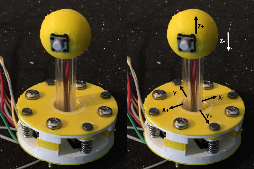
The mounting starts by connecting the coloured electrical wires to the 6 mini push button switches. Yellow wire for [X+]; Orange wire for [X-]; Green wire for [Y+]; Blue wire for [Y-]; Red wire for [Z+]; Brown wire for [Z-]. The grey wire is commonly used to power the button presses, either through Ground or Vcc, depending on the final application and associated electronic assembly. This colourful assembly simplified the visualisation of the connections after the final assembly of the joystick :

Step 2: The Base
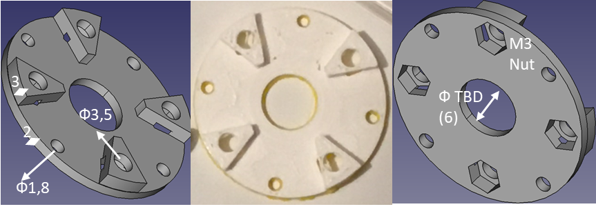
The base mainly houses the mini push button switches and M3 nuts, which secure the final assembly. It features a 40 mm diameter and 2 mm thickness disc, with four 7 mm square compartments located 15 mm from the center. These last compartments hold the push buttons that measure 6.5 mm on each side. The central points of these switches are located approximately 12mm from the centre of the base part. Each square has four 2mm diameter through holes for positioning the pins and wires of the push button. Additionally, four 1.8mm diameter holes for the spring axes, required for the reversible movements, are located behind the push button housings. Four 4mm spacers enable the top base to be adjusted to the required distance for unrestricted movement along the X and Y axes. Each spacer has a 3.5mm diameter through hole for the placement of an M3 screw, which secures the assembly with a nut housed in a dedicated housing on the back of the base part. 
Attachments
Step 3: The Mobile Plate
The half-spherical ball joint of the mobile plate is centered on the base part. The half-spherical ball has an 8mm diameter. The center features a 4mm through-hole that is used for wiring [Z+] and [Z-] as well as the common power supply. The function of the moving plate part is to press the switch buttons. It achieves this through 4 hemispheres with 6 mm diameters placed over the switches, positioned precisely 12 mm from the center. These hemispheres are situated 8 mm from the end of a 40 mm-long, 5 mm-wide, and 2 mm-thick branch. The ball joint housing is situated at the centre of the component. The cylindrical housing measures 10mm in diameter and 6mm in height, with a central cavity of 6mm diameter for the ball joint. A 4mm hole runs through the centre of the component to enable the [Z+][Z-] wires and the common power supply wires to pass through.

Four holes, each measuring 1.8mm diameter, allow the spring axes to be positioned. The four springs provide reversible mobility by relying on the mobile plate on one side and the base on the other.

Attachments
Step 4: The Top Component
The top component, the upper part, resembles the base component. It is a 40 mm diameter disc, with a thickness of 2 mm. The holes for the M3 screws and spring axes are located there. Four 3mm high spacers allow the base of the top to be moved to the distance required for free movement. These spacers have a 3.5 mm diameter through hole to accommodate the M3 screw that secures the final assembly with a nut located on the back in dedicated housing. In the centre of the structure, there is a space for the [Z+][Z-] axis rod to pass through. The size of this space is dependent on the rod being used and, in our example, it is a 6mm diameter hole to allow a pen tube to pass through.

Attachments
Step 5: The [Z+][Z-] Rod Head
The joystick's end section is the rod [Z+][Z-] head, which contains the two buttons for displacement along these axes. This spherical head is made up of two half-spheres of 10 mm diameter with cubic cavities of 7 x 7 mm² for the push-buttons. One cavity is used to secure the axis, which is the pen's tube with a diameter of 6 mm.

Two 1.8mm diameter holes enable you to insert a piece of 3D printing PLA wire to simplify assembly of the sphere. Start by securing the PLA rods into the holes, then insert the buttons into their respective cavities. Finally, bond the entire assembly around the pen's tube with cyanoacrylate glue (super glue).

Attachments
Step 6: The Final Assembly
The assembly is mounted using M3 screws and nuts and cyanoacrylate adhesive. If required, a final box and suitable 7 connectors can be added to complete the assembly.

Editor's note : Two colours (white and yellow) of PLA were utilised in this equipment merely for photographic and contrast purposes.
Step 7: X, Y, XYZ Joystick ON/OFF Is Activated in Pull Up Mode for an Arduino Control Card.
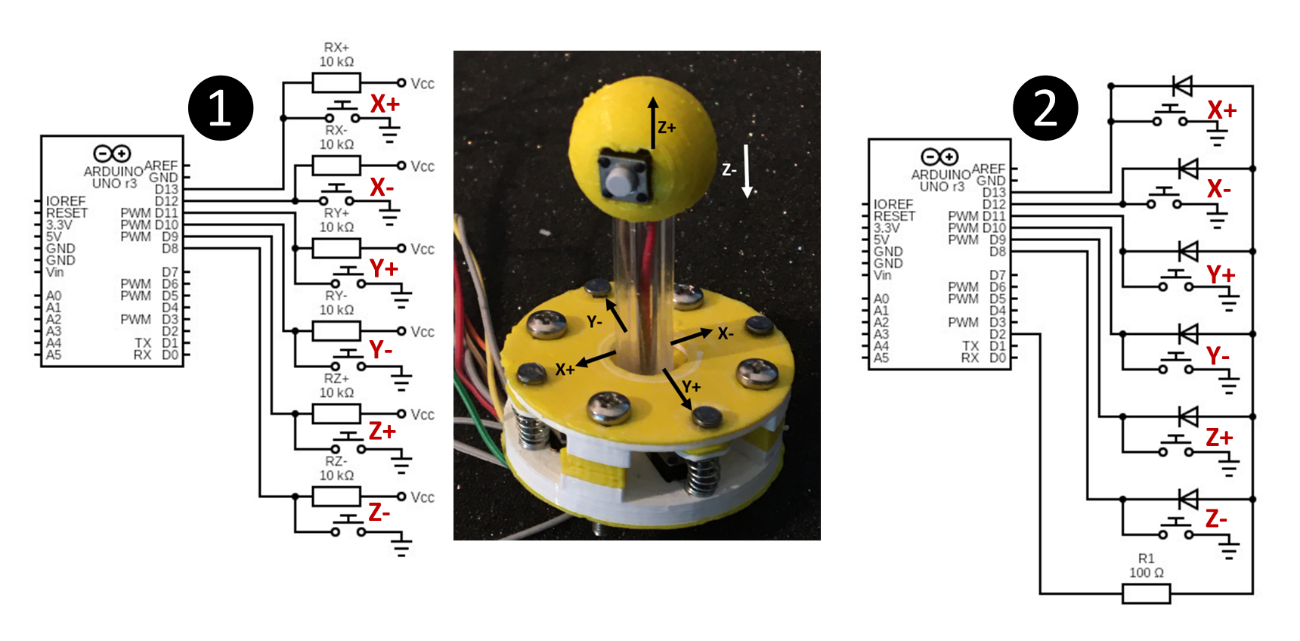
Connecting an ON/OFF joystick for X, Y, and Z directions in pull-up mode to six pins of an Arduino is the most basic method of control. In this configuration, the common power wire is grounded. At rest, the pins are in the high position (Vcc – HIGH). When the joystick is activated in any of the six directions, the associated pin is grounded (Ground – LOW). The transition of pins [X+];[X-];[Y+];[Y-];[Z+];[Z-] from [1/0] to [HIGH/LOW] or [Vcc/Ground] provides the requested information for controlling the equipment connected to the joystick.

Two arrangements exist for a pull-up assembly:
Configuration ❶ employs six 10 kOhm resistors, which are connected to the voltage of the Arduino (5 or 3.5 V). When the button is not pressed, the voltage at the Arduino terminal has the value [Vcc]. When the button is pressed, the input drops to 0 V value, and a very small current of about 0.5 mA (Vcc/R) flows through the resistor, which does not damage the circuit in any way. Changing the pin state from [HIGH] to [LOW] allows the detection of the activation of one of the 6 joystick setups.
Configuration ❷ permits, in addition to detecting the activation of one of the 6 joystick configurations, to detect a pulse on pin [d2] of the Arduino and thus to interrupt the progress of a programme as soon as one of the 6 joystick connections is activated. Each joystick output is connected to a separate pin (d8 to d13 in our example), all of which are connected to the interrupt pin. Using a diode, all these pins get connected to the interrupt input pin [d2]. Unlike the initial scenario, all the pins involved have been set to "INPUT" and "PULLUP" modes. "PULL-UP" set all the pins to a [HIGH] state thank to the Arduino internal resistance while the “INPUT” mode allows the Arduino to receive data. The diodes provide protection against the switch's actions affecting other pins. This double mode is activated in the program's "setup" section by writing "pinMode(BUTTON_PIN, INPUT_PULLUP);". When a switch is pressed, the corresponding pin is set to a low state [LOW], and the interrupt detection pin (d2) follows. The diodes serve to safeguard against other pins being affected by the switch's action.
See our book on sensors for other possible circuits to reduce the number of Arduino spins in use, or to control DC motors or stepper motors.
Component parts :
Configuration 1 : Joystick XYZ, RX+ = RX- = RY+ = RY- = RZ+ = RZ-= 10 kΩ, Arduino
Configuration 2 : Joystick XYZ, DX+ = DX- = DY+ = DY- = DZ+ = DZ-= 1N4004, R1= 100 Ω, Arduino


![Tim's Mechanical Spider Leg [LU9685-20CU]](https://content.instructables.com/FFB/5R4I/LVKZ6G6R/FFB5R4ILVKZ6G6R.png?auto=webp&crop=1.2%3A1&frame=1&width=306)


