UV Two-sided Exposure Box

19,106

266

38

Introduction: UV Two-sided Exposure Box

Hi There!

This is my first post :)

On this site I saw a few projects UV Exposure Box, and decided to make my choice ... I decided to share with you :)

I wanted to have a two-sided exposure box. I used MDF 12mm and cast acrylic 3mm to prepare the body

Also I have prepared PCB, Proteus 8 with professional help, share all the required filters and information needed to prepare.

Then I'm going to add Fan Air Heater Temperature Heaters to dry

Step 1: PCB UV Timer Creation and Parts:

PCB has developed, Proteus 8 professional help because everyone can not have this program, share PDF files as well as original files Proteus 8

TIMER pcb parts:

arduino nano (1)

relay 12v (2)

buzzer (1)

CONNECT PIN5 2.54(1) for ENCODER modul arduino

CONNECT PIN3 2.54 (1) for buzzer

TERMINAL BLOCK P2 5MM (12)

led 3mm (inticator) (3)

transistor Power MOSFET IRFZ44E (1)

transistor 5V 1.5A Linear Voltage Regulator 7805 (1)

pcb potentiometer 10K (1)

Ceramic Capacitors 0.1uf (4)

resistor 10K (3)

resistor 300 (3)

resistor 22k (1)

resistor 680 (1)

resistor 100 (1)

Step 2: PCB for UV LED Board

I decided to prepare the UV LED board in four parts of size 15X20 cm,

Because it was possible to produce different size UV Exposure Box The distribution of the boards in my case, the pairs are above and the pair below, the total size of 20x30 cm ... A4 format

It's also easier to make this size than 20x30cm

LED board parts: (board 15X20 CM) You need 4 pieces

resistor 91 (36)X4

UV LED 3.2-3.6V 20mA 395nm - 400nm 5mm (108)x4

Total: resistor 144 pieces and LED UV 432 pieces

Step 3: Body Creation and Parts:

Apply the material to the MDF 12 mm, the size of which is given below, click on the cnc machine, if you have a CNC, I can share files for cnc svg format or CorelDRAW

Body parts:

material MDF 12mm

Dimensions and drawings can be viewed in PDF format "Dimensions and drawings"

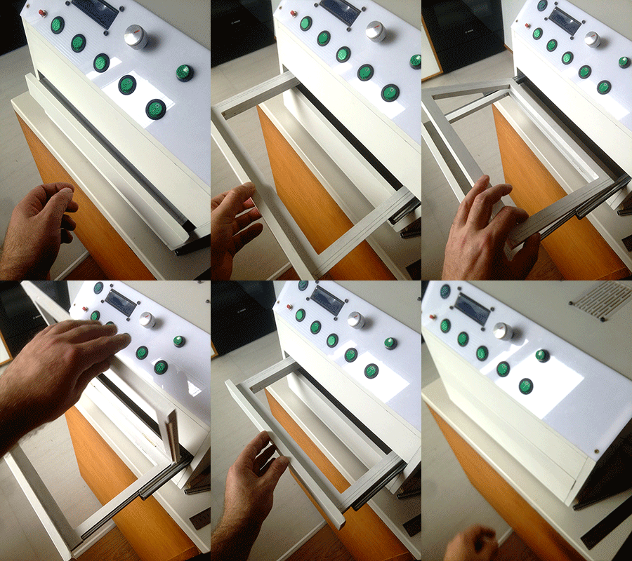
4 pieces 180mm Metal Full Extension Ball Bearing Drawer Slides Smooth Runners (The pair must merge, because the tray is open completely)

UV Exposure Box


Step 4: Control Panel Creation and Parts:

control panel Made cast cast acrylic 3mm,

control panel placed: LCD screen, ENCODER modul arduino time control, inclusion keys, controlled upper and lower leds ... Also relay Led lighting Added 110-220v relay, for instance if you use 110-220v lamps, which are also controlled by ...

One of the output signals for RELAY, which can be accessed by Reale Fan Air Heater Temperature Heaters to dry

Step 5: Finish

The final look

If you are interested and you have the idea to be better, please share it :)

First Time Author Contest

Participated in the
First Time Author Contest

Box Contest 2017

Participated in the
Box Contest 2017

Be the First to Share

    Recommendations

    • Make It Bridge

      Make It Bridge
    • For the Home Contest

      For the Home Contest
    • Big and Small Contest

      Big and Small Contest

    38 Comments

    0
    Jeanmi
    Jeanmi

    1 year ago

    Hello dear GiorgiQ

    I contact you because i have find your project Uv isolation and you make very good work

    I want create the same box, but i need help for the pcb build, i see your files is extension jpg, but i don't know how make for order somewhere all the pcb for building the uv isolation, can you explain me 😅
    You can contact me at jmofpattaya@outlook.com
    Sorry for my English
    Thanks you

    0
    GiorgiQ
    GiorgiQ

    2 years ago

    Unfortunately, I could not find the files ...
    Can't download from here? :(

    0
    inkl
    inkl

    3 years ago

    Hi! Very good project. I've decided to build one. But where are the circuits schematics? For the timer and the LEDs. Thank you!

    0
    markus24
    markus24

    Question 4 years ago

    Hello, the .ino file for the arduino is invald and could not be open. Could you please send me the code to markus.berger1298@gmx.at? Thanks!

    0
    traskutys
    traskutys

    Question 4 years ago

    Hi, I am going to build your project and I have some questions for you, can you contact me traskutys16@gmail.com ?

    0
    GiorgiQ
    GiorgiQ

    Answer 4 years ago

    I wrote you, what are you interested in?

    0
    WahedM
    WahedM

    4 years ago

    Please ... I need the circuit diagram ... the image on the page is not clear
    THANK YOU VERY MUCH

    0
    WahedM
    WahedM

    Reply 4 years ago

    Thank you very much

    0
    jarda-burian
    jarda-burian

    Question 5 years ago

    And what About these extra holes in timer PCB?

    0
    jarda-burian
    jarda-burian

    Question 5 years ago

    I do not understrand why there are two buzzers and one has three pins, I bought that piezo and it fits into that two-pins one, so what About these three pins? Thank you. And the display, are there any special specifications? Thank you so much.

    0
    jarda-burian
    jarda-burian

    Question 5 years ago

    What is that RV1 on PCB please?

    0
    GiorgiQ
    GiorgiQ

    Answer 5 years ago

    V1 Resistance 10k. Controlling the display contrasts

    0
    jarda-burian
    jarda-burian

    Question 5 years ago

    What is the power supply?

    0
    jarda-burian
    jarda-burian

    Answer 5 years ago

    It looks like 230v, but I see any power supply in the box, or am I wrong?

    0
    GiorgiQ
    GiorgiQ

    Answer 5 years ago

    I used the 12 volt power supply in 20 ampers, 230 volts ... enough 4 amperes, 5 amperes are desirable.

    0
    GiorgiQ
    GiorgiQ

    Answer 5 years ago

    12 volt, minimum 4amp..

    0
    jarda-burian
    jarda-burian

    5 years ago

    Hello, do I need a premium account to get all steps or is it all in article?

    0
    GiorgiQ
    GiorgiQ

    Reply 5 years ago

    You do not need to have 5 steps, if you have any questions you asked me to answer