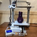
Introduction: Upgrading 3D Printer From 12 to 24 Volt
My CoreXY is a beast. It has 4 2A stepper motors, 4 TMC2130 stepper drivers, 110 Volt heated bed, enclosed case and for almost 3 years now has been running on a 12 Volt knock off RAMPS 1.4. It's like a corvette running on a corolla engine.
There is anecdotal information about things heating up faster (which I'm not convinced of as you will change the heater cartridge) but most importantly, I've read that TMC2130 Stepper drivers operate better on 24 Volt and stepper motors have more torque when upping the voltage.
If anything, as you can see from the images above, upgrading to 24 volt certainly has made me revisit my wiring. That alone brings a feeling of immense satisfaction.
In this instructable I will discuss the 24 volt upgrade of my printer which is a CoreXY with 2 2A steppers, 2 1.7A steppers, Direct extrusion, parts cooling fan, controller cooling fan and LEDs.
In my upgrade I'm using a KFB2.0 controller board but there are many other alternative boards that can handle 24 Volt. The RAMPS 1.4 happens to be one that is not built to handle 24 Volt (there are upgrade options to that).
Many of the items will be similar in your printer and might be handled the same.
Step 1: Safety First
At this point I have to point out that, even though 24 Volt is not lethal, the power feeding it, from your wall IS. Dealing with electricity is dangerous (especially for you non-US, double the 110V, readers). Do not do this if you don't know what you're doing.
There are also settings within your 3D printer firmware that are supposed to help in keeping your printer safe (like thermal runaway protection). Make sure your 3D printer is up to date and configured with safety in mind.
Step 2: Know Your Current Wiring
It so happens that my printer had a bunch of wiring all over, many of it bundled, making it hard to trace back.
It is imperative that before doing anything, you've identified all wiring. If your lucky and your board can handle 24 Volt then most wiring may remain in place, but if the upgrade involves changing boards, things can get complicated.
Above image shows the mess that was my wiring. On top of that I used a DB25 connector to connect all my wiring to the Extruder Assembly (Heater Cartridge, thermistor, nema17, inductive sensor, cooling fan and parts cooling fan).
Take notes (doesn't need to be anything fancy, as you can see from the images) and add some markers using blue tape identifying what goes where.
Another thing to take note of is how your stepper motors are connected to the board. On the board the pins are generally identified as "2B 2A 1A 1B". If your changing boards, re-crimp your wires or order different wires (going from dupont to JST-XHP) make sure the wires line up.
From what little is left of my electronics education, more voltage is lower current, so in general your current wiring should suffice when upgrading.
Step 3: What Do I Need
Obviously the first thing you'll need is a 24 Volt power source to replace your existing power unit. Chances are you have a universal switching power unit (as seen in the image above) that comes in both 12 volt and 24 Volt versions (same price too).
24V 15A DC Universal Regulated Switching Power Supply 360W: Amazon $17.99 https://amzn.to/2sRqDwz
24 Volt Hot-end heater cartridge: Amazon $8.90 https://amzn.to/2JqJJDQ
Now before you say, wait a minute, If I use my 12 Volt cartridge won't it heat up faster? Probably yes, but at the power it is rated at, the temperature can get so high, it will melt your heat block. Safety first!!
My printer has a 110 volt heated bed that is controlled via the bed port on the controller connected to an SSR (solid state relay). The SSR can take in voltage anywhere from 3 to 32 volts so I didn't have to change anything. See the instructable on that upgrade here.
If you have one of the common MK2 heated beds, you can generally wire them for either 12 volt or 24volt. There's is little table depicted on these beds on what pins to supply power to based on 12 or 24 volt.
Step 4: What About the 12 Volt Components
Yes, I realized that one as soon as I clicked "order now" on my power unit. wait a minute, my LEDs are....
My printer has 4 fans, all 12 Volt and 12 volt LEDs lighting my printer. Do I replace all of those? Not necessarily. You have some options here:
- Running, 12 Volt fans on 24 Volt will make them go fast and probably damage them in a short matter of time.
- Running 2 fans in series. This seems to be recommended quit a bit out there (if you have 2 to run in series). There's pro's and cons to that (if one fan is obstructed, it will draw power away from the other fan, is one con I can think of).
- Buy 24 volt fans. This is certainly an option:
- 40mm (generally for cooling hotend/parts) Amazon $12.98 (5 pack) https://amzn.to/2Pys63B
- Compartment cooling fan:Amazon $7.99 https://amzn.to/2NNfuoQ
- Blower Fan (generally used for parts-cooling): Amazon $12.99 (2-pack) https://amzn.to/2Q2vZ1L
If you're a nut for the super quiet Noctua fans (like I am), there is no 24 Volt alternatives. In my case I opted for converting 24 Volt down to 12 Volt where I needed to using LM2956 dc to dc converters Amazon $7.99 (6 pack) https://amzn.to/2t1aeEG
For the parts cooling fan which speed is controlled by the controller, I choose to change the software a bit to make sure that when sending speed (m106 S255) the S value would always remain below 128
Marlin_main.ccp (fanSpeeds[p] = min(s/2, 127);)
inline void gcode_M106() {
    const uint8_t p = parser.byteval('P');
    if (p < FAN_COUNT) {
      #if ENABLED(EXTRA_FAN_SPEED)
        const int16_t t = parser.intval('T');
        if (t > 0) {
          switch (t) {
            case 1:
              fanSpeeds[p] = old_fanSpeeds[p];
              break;
            case 2:
              old_fanSpeeds[p] = fanSpeeds[p];
              fanSpeeds[p] = new_fanSpeeds[p];
              break;
            default:
              new_fanSpeeds[p] = min(t, 254);
              break;
          }
          return;
        }
      #endif // EXTRA_FAN_SPEED
      const uint16_t s = parser.ushortval('S', 254);
      fanSpeeds[p] = min(s/2, 127);
    }
  }
In my conversion I have 4 LM2596 deployed:
- 1 for LEDs
- 1 for Power unit cooling fan (yes, I even replaced that one with a Notua fan)
- 1 for Hot-end cooling fan
- 1 Controller cooling fan (optional for most 3D printers).
Step 5: DC to DC Converter
The LM2596 DC to DC buck converters are pretty easy to use little gadgets to get the right voltage you need.
Simply apply the power to the input connect a volt meter at the other end and turn the little screw to get to the voltage you need.
But.... When I connect a LM2596 to my PWM output, which by sending it the proper speed, should set the output voltage higher/lower, did not work with the LM2596. The PWM output on my controller automatically reverted to 24 volt, regardless of what speed (0..255) I sent it. This I'm guessing because you're not really changing voltage but instead sending it different pulses.
I didn't dig much deeper and instead changed the software to simply half the PWM I would send to the fan.
Someone did point out that there's a way of connecting the Buck converter. I have additional LM2596's on order and once I get them I'll try that out. I'll keep you posted.
I've added 4 dc to dc converters to my printer for several reasons.
- The LM2596 needs to keep the Amps below 2.5. Even though my fans, use barely any, the LEDs can pack a punch
- I want to be able to play with the voltage to my fans. They're rated for 12V but if I can send a little less they get a little more quiet.
- By having seperate LM2596 on different fans I can control them individually.
Step 6: Organizing Wires
Organizing the wires is not a necessity when upgrading your 3D printer but boy... It looks good and it also makes it easier to swap out components.
I did have to replace several dupont connectors with JST-XHP connectors.
For organizing the wires I applied mini zip ties where ever needed. By adding zip ties in the proper places you can kind of "sculpt" the wires in place. I also drilled lots of holes in my bottom plate to tie the wires down permanently.
When I first posted pictures of this wiring on the 3D printing facebook page, members where impressed but some electricians immediately pointed out, I shouldn't have screwed in the wires as is into the screw connectors. I should have used either ring cable lugs, ferules and/or fork terminals.
I haven't gotten to the ferules yet but everything else now has fork connectors.
Here are all the tools and parts needed for wire managent
mini zip ties: Amazon $6.48 https://amzn.to/2LIExb0
JST connectors were all 2/3/4 pin connectors set: Amazon $9.87 https://amzn.to/2JIFjYd
If you don't have one yet the crimping tool for JST-XHP Amazon $22.99 https://amzn.to/2y3Ktts
ferules kit (comes with proper crimping tool): Amazon $25.89 https://amzn.to/2Jy3oSB
Fork terminals: Amazon $6.69 https://amzn.to/2JqRcmi
Step 7: Upgrading/Conclusion
Once you have all the pieces in place from the previous steps, upgrading is a matter of connecting all the wires.Connections are no different then when wiring 12 Volt power.
You can find the wiring instructions for the KFB 2.0 here
Was it worth it? It depends, the printer on the outside looks the same as it did. On the inside it looks awesome (which makes me happy I put a drawer mechanism in) but that is not due to 24 Volt. I just finished a 20 hours and 2 minute print and it worked great. It did however before so it's hard to judge.
I'll have to keep you posted on what I find going forward.
It was a fun exercise but before you embark on this don't be surprised if the result is somewhat underwhelming.


