

Introduction: 12-24v DC Motor Controller Using an EC1 SPLat PLC


There aren't many simple programmable DC motor controller instructions out there but now I bring you step by step instructions on how to make one that can be expanded for use on robots to a 500W electric go cart!
(note this instructable only shows how to make a simple controller for 10A max)
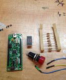
Parts you will need:
1 EC1 SPLat PLC available from SPLat
1 DC motor >10A at 12v (this controller WILL work on 24v but for all intensive purposes I will show on 12v)
2 TO220 heat sinks with screws and insulators
1 Perf board
2 240 ohm resistors
1 220 ohm resistor
2 1k ohm resistors
1 PNP transistor (4430 is what i use)
2 LM317T pos voltage regulators
1 10A or higher 24v or higher MOSFET (I use the IRF3205 wich is 110A at 100v)
2 5k ohm trim potentiometers
1 5k ohm regular potentiometer
solder
soldering iron
wire
female header connectors
wire cutters/strippers
A computer running SPLat/PC, the free SPLat programming environment (IDE)
Step 1: Schematic

Above is the schematic for this entire circuit including the exact pin out of the EC1 when looking from the top
The regulator powering the EC1 should be tuned to 5V and NO MORE 4.8 is ok 4.9 is ok 5v is ok but just to be safe and not fry the EC1 do not go above 5v
The regulator that powers the switching circuit should be between 9.5v and 10v
Step 2: Place the Components


I recommend separating the the LM317 from the MOSFET enough that the heat sinks cannot accidentally come in contact with each other to avoid problems.
I also recommend placing the TO220s in their heat sinks before soldering
Now go ahead and solder them in place once you have positioned them and trim the leads
Step 3: Place the Components (cont)


Now lets start with the Regulator
Place the 240 ohm resistor from the adjust (far left pin) to the output (center pin) and solder the connection
Now position the 5k trim pot in the best way so that the adjust of the lm317 is on the center wiper of the pot and one end is near were you think your common negative will be and solder its connections
We will make another one of these regulators next to this one and connect their negatives together (the one end on their trim pots) and their positive inputs together (the far right pins) Also it is not necessary but recommended that you use a heat sink on the regulator powering the EC1!
Step 4: Making the Switching Circuit

Now that we have our two regulators set up we will choose what one we want to power out switching circuit and tune it to 9.5 - 10V
lets begin with placing the PNP transistor (4403) near the regulator but not oo close and solder it in place.
Now connect the input terminal (far left) to the output of the regulator and connect a 1000 ohm resistor to the center pin on the transistor and place the unused end of the resistor in an open area near the edge of your board were it is easy to get to and solder it there
Step 5: Make the Switching Circuit (cont)

Now that we have our switching transistor in place we will connect a 220 ohm resistor from its output (far right) to the trigger of our MOSFET (far left pin) and another 1000 ohm from the trigger to its input (far right pin) and connect its input to our common negative. * make sure this connection is capable of carrying your MAX current that the MOSFET is capable of*
Step 6: Wire Connections

Now we must solder our wire connections that connect to the EC1, Power, And our motor.
Lets start with the Power input and output, solder your main supply negative to your common that you created by soldering all of your negatives together and solder your main positive input to the two regulator inputs that should be connected already.
Now solder a lead from your positive in to either your motor or somewhere on the board near your MOSFET so that you can connect one motor lead to it and do the same to the output of your MOSFET (center pin)
*Note this wire must also be capable of carrying the MAX current capable of the MOSFET*
Step 7: EC1 Connections


Lets solder one of our female header connectors to the negative and one to our output of the second regulator (making sure it is set to 5V)
Now solder one more to that unused resistor lead that we left open earlier.
Think your done? Not yet you will need three more, soldering one to each terminal on the regular potentiometer.
Step 8: EC1 Connections (cont)

Now lets plug it all in to our EC1
Connect the positive and negative connections to the 5V and 0v pins on the EC1
Now connect the trigger connection (the one connected to the resistor) to Pin 0
Finally connect the potentiometer one end to positive 5v and one end to 0v then the wiper (center) to pin 3
Step 9: Write the Program

Now plug in the EC1 to your computer via USB and open SPLAT then connect to your EC1
I am going to start with a very simple program.
the programming language for all SPLat PLCs is very simple the PWM (pulce width modulator) output we are using is pin 0 so analog output 0 or ANOUT 0 and the analog input is pin 3 and is identified as ANIN 0
by placing an F infront of these functions will make the EC1 read from analog input 0 (or 1 or 2) with Fanin c+, or output the stored value in its memory to the analog output 0 (or 1 or 2) with Fanout c+
So if we type:
start
Fanin 0
Fanout 0
goto start
running the program will read the value of the pot 0v being 0 and 5v being 1 (so .01, .02 .03... these are in floating point or FP for short) it will then store that FP value in its memory and output the value in the form of a pulse width on analog output 0 which triggers our motor to GO IE: higher FP number = faster motor.
If all you want is a simple motor controller then here it is you are done but if you want to expand or see what else can be done check out the next step!
Step 10: Add Ons
So expanding on what was previously stated with:
start
Fanin 0
Fanout 0
goto start
we can now add things like:
motor
fanin 0 ;reads analog input 0
fgoifnz motor ;goes back to motor and reads again if it is not equal to 0
MM fanin 0 ;reads input again
floadq -0.01 ;loads memory Q with the value -0.01
fadd ;Adds W to Q and leaves the result in W. Q is unchanged.
fgoifneg mm ;tests the contents of the floating point register W, transfers program control to the ;destination LLLL if W<0
fanout 0 ;outputs the value in W to analog output 0
goto MM ;transfers program to MM
This has two changed parts, first being that before the EC1 starts to output a pulse to the motor the pot has to be turned to zero so that the motor cannot take off on you
The second change is that you can now adjust for your wire resistance because if you plan on having the pot more than 6 inches from the board it will begin to detect the wire resistance as an input and start to output 0.01 0r 0.02 when the pot is at zero. we adjust this with that negative FP value -0.01, we can make it -0.02 or -0.03 and so on until the motor is completely off when the pot is at zero.
Another cool thing we can do especially for autonomous robots is by using the FloadQ and Fadd functions we can make a loop that will slowly increase or decrease the motor speed based on external inputs for example buttons, sensors, microphones, or any other external interaction or a simple loop that is continuous in a pattern IE: speed up slow down speed up slow down...
The EC1 can output to a relay with a transistor to change direction of the motor as well and can perform multiple tasks at once to monitor sensors or output multiple things at once.
I hope you enjoyed this instructable! please feel free to comment with questions comments or concerns and feedback is greatly appreciated! you can find more about how to order, program or interface the EC1 on the SPLat website

![Tim's Mechanical Spider Leg [LU9685-20CU]](https://content.instructables.com/FFB/5R4I/LVKZ6G6R/FFB5R4ILVKZ6G6R.png?auto=webp&crop=1.2%3A1&frame=1&width=306)


