

Introduction: COI - Party Lighting


More by the author:


About: ABOUT FCFI FCFI is a community oriented public workshop where people can meet and work on their projects. We provide a facility that is open 10 AM to 10 PM, 6 days a week (with plans to eventually be open 24/7…
Hardware:
- Intel Edison
- Static Mat
- Computer
- 2 Mini USB Cables
- 2 Jumper Cables
- 3 LED Lights (1 blue, 1 green, and 1 red)
- 3 1000 OHM resistor Bread Board
- 4 Pin Cables
- Seeed RGB Backlight LCD
- Seeed Rotary Angle Sensor
Setup:
- Plug in Grove base shield into your Edison(doesn't have to be an Intel Edison,it can be an Arduino board )
- Plug jumper cable into port I2C (doesn't matter which one). Connect other end to RGB Backlight LCD.
- Plug 1 of the jumper cables into the 5V port on the Edison. Connect to the bread board. (See picture for reference. It's the blue cable closest to the 12C cord you just plugged in.)
- Plug other jumper cable into port A0. Connect other end to Rotary Angle Sensor.
- Plug other 3 jumper cables into ports ~3, ~5, and ~6. We will connect these to the red, green, and blue lights respectively.
- See diagram of bread board for details on what wires go where.
- Download code at the end of the page.
- Upload the code into Arduino IDE.
- Upload the code into Edison.
- Play with the Rotary Angle Sensor. Enjoy the pretty lights!
Software:
Open the Arduino Edison IDE and use the following code:
#include
#include
#include

rgb_lcd lcd;
int bluePinNum = 6;
int greenPinNum = 5;
int redPinNum = 3;
int potentiometer = 0;
int minPotValue = 0;
int maxPotValue = 1024;
//NOTES: PINS PRECEDED WITH A TILDE ARE ANALOG, AND OTHERS ARE DIGITAL.
//OUTPUTS ARE INVERTED IN OUR SETUP. I.E. 0 IS FULL BRIGHTNESS, 255 IS LOW.
void setup() {
  lcd.begin(16, 2);
  lcd.setRGB(255, 255, 255);
  pinMode(potentiometer, INPUT);
}
void loop() {
lcd.setCursor(0,0);
//lcd.print(analogRead(potentiometer));
//lcd.setCursor(0,1);
double read = analogRead(potentiometer);
double fraction = (read - minPotValue)/(maxPotValue - minPotValue);
fraction = fraction - floor(fraction);
//lcd.print(fraction);
double sixth = 1.0/6.0;
int r = 0;
int g = 0;
int b = 0;
if(fraction < sixth){
r = 255;
g = (int)((fraction)/sixth * 255);
} else if(fraction < 2 * sixth){
r = (int)((2 * sixth - fraction)/sixth * 255);
g = 255;
} else if(fraction < 3 * sixth){
g = 255;
b = (int)((fraction-2*sixth)/sixth * 255);
} else if(fraction < 4 * sixth){
g = (int)((4 * sixth - fraction)/sixth * 255);
b = 255;
} else if(fraction < 5 * sixth){
b = 255;
r = (int)((fraction-4*sixth)/sixth * 255);
} else {
r = 255;
b = (int)((6 * sixth - fraction)/sixth * 255);
}
analogWrite(redPinNum, 255 - r); //because of inverted values
analogWrite(greenPinNum, 255-g);
analogWrite(bluePinNum, 255-b);
lcd.setRGB(r,g,b);
}Verify and Upload the Code.
Result:
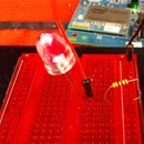
Your finished product is a “Party Lights”. It changes the color of the LCD screen. This same technology can be used by people with disabilities to signal for help, or it can be used in the workplace as a signal between workers or in a factory line.
Experience:
There are a number of pitfalls that should be avoided when doing this project.
- Always use the static mat, as charges can accumulate on the electronics or your body if not properly grounded, and this can damage the electronics.
- Make sure the ports on the Grove Starter Kit Plus Base Shield are the same as the ones used in the picture. If not, the address used in the code will not be able to access the button.
- Check the connections on the components to ensure failure is not due to a hardware problem.


