

Introduction: Teaching Mike to Walk


This is a 3d printed, Arduino controlled, six degrees of freedom, walking robot. Well--sort of. He walked better on an umbilical cord than with his fat stomach and big head (sounds like some people I know). More about that later.
The concept was to make a smart walking base that would accept controls from upper modules (head and arms).
Step 1:


Let's start with what was done well. I used MG996 Servo motors, high torque and less than ten dollars each on Amazon.com. I numbered the motors "4" through "9" and marked that number on the visible face of each motor. The numbers on the motor correspond to the Arduino pin number and the software description. Thus, Servo motor "4" goes to pin "4" on the Arduino and is called "S4" in the software.
To walk, I first had to shift the weight so that it was centered above the left foot. This involved moving motors "4,5,7 and 8." This is followed by lifting the right foot (motor 7 on the left foot).
Next, the right foot needs to move forward and this is accomplished by using motor "9." Because the body twists, motor "6" must be operated to keep the right foot straight.
Next, the right foot is lowered, then weight shifted, left foot raised, moved forward, etc.
Attachments

Step 2:
Print all the 3d body parts.
Attachments


Step 3:


Center all the servo motors to the 90 degree (midway point) for mounting. Mount numbers "6" and "9" on the body cage.
Step 4:

Attach the servo horns to the hip brackets using 2-56 machine screws. Push the hip brackets onto the servo motors, then fasten with the servo horn screw.
Step 5:

Attach motors "5" and "8."
Step 6:

Attach the servo connector (printed) to servo motors "4" and "7."
Step 7:

Attach the other end of the servo connectors to the servo horns from motors "5" and "8."
Step 8:

Add a switch to the "slide in" controller level.
Step 9:

Install the batteries, battery spacer and "anti-slide" bracket in the lowest level of the cage.
Step 10:

Attach the Arduino and breadboards to the controller level.
Step 11:

Create a wire harness that connects the servo motors to the Arduino (schematic back in step 2).
Step 12:

Tie wrap the wires from "4, 5, 7 and 8" to the frame so that he won't trip.
Step 13:


Load the software, connect the wires and add the head.
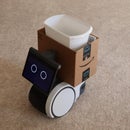
Step 14:

Now, he looks marvelous, but doesn't walk so well.
What I learned:
1) Adding batteries, electronics and a head (above the legs) impacts the center of gravity. Movements have to be slow and respect this situation (this can be managed in software, though he may turn into a "shuffler" rather than a gallant walker).
Step 15:

2) You can't power six servo motors through one "not so tight" pin on a breadboard. The breadboard is great for connections, but if you try to power a bunch of servo motors then expect the shakes and weird movements.
Step 16:

3) As you add more and more weight topside, there is a lot of stress on the lowest shaft connection.
Hopefully I can address these issues in future (stronger) legs.
Update 8 P.M. 1/12/15 The software in this step will walk without falling down.
Attachments

Participated in the
3D Design Contest


