

Introduction: UFO, Upush Flashing Object


The generator powered lights on this ufo flash when it is pushed forward. The 3d parts were designed using Fusion 360 (I downloaded the software 4 days ago) and I have included the Fusion files as well as a tutorial for modifying a part (step 17).
Step 1: Parts
This is mostly printed--but there are other parts involved:
Motor/generator Dagu Gear Motor
(1) 2-56 x 1 1/4 inch machine screw and nut
(2) 2-56 x 10 mm machine screws (fasten wheels to axle)
(2) M3 x 12 machine screws (top to saucer body)
(2) M3 x 16 machine screws (saucer body to base)
Misc: wire wrap wire, solder, heat shrink tubing
3D printing parameters
Print at 100% fill: axle support, body3, (8) led holders, rear wheel, topb, (2) wheels
Print at 30% fill: saucer body, saucer top
Attachments


Step 2:


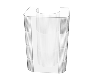
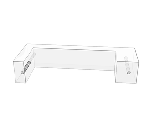
The rear wheels, axle support and body look like this.
Step 3:


Place the rear wheel assembly in the channel in the axle support, then melt the axle support to the body. I melt the PLA pieces together using a soldering iron.
Step 4:

Place the motor inside the body--note the little "nub" on one side of the motor that fits into the body.
Step 5:


Secure the front of the motor using the 2-56 x 1 1/4 inch machine screw. Tighten the nut on the machine screw, then cut the excess part of the screw off (don't forget to use goggles when "nipping" metal).
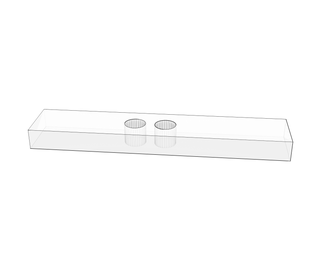
Step 6:


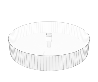
Print the saucer base and saucer top.
Step 7:

Thread the M3 screws into the receiving holes--sort of makes threads.
Step 8:


Attach the top to the body by melting together with a soldering iron.
Step 9:


Cut a thin strip of duct tape and add it to the wheels for traction.
Step 10:

Using the 2-56 x 10mm screws, attach the wheels to the axle on the motor (the motor is being used as a generator).
Step 11:

Test the flashing leds to be sure that they work. It will be a pain to complete the assembly and discover a "dead" led; so just check them out now.
Step 12:


Place the leds in the led "holders." The notch on the led will prevent it from moving outward through the hole and the "holder" will prevent the led from coming back inside the body.
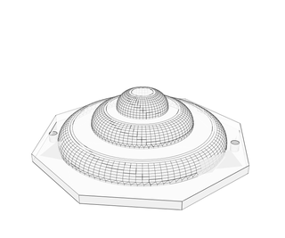
Step 13:

Check the holes in the saucer body and be sure that the leds will fit. If they are too tight, ream them out with a 13/64 inch drill bit, then paint the saucer body and top.
Step 14:


Melt the led holder to the saucer body using a soldering iron.
Step 15:


Wire the leds in parallel using wire wrap wire.
Step 16:

This is my personal "standard" for keeping up with polarity sensitive items (like leds). When I don't have enough colors of wires (often), then I tie a loose loop on the end of the wire that needs to be connected to positive
Step 17:

I needed another hole in the saucer base to prevent the motor wires from getting tangled in the wheels. I just drilled a new hole using a 13/64 inch bit rather than redesigning and printing the saucer base.
However, below I show you how to use Fusion 360 to add the hole:
Step 18:

Bring the motor wires up through the hole and fasten the saucer base to the top of the motor assembly using M3 x16 screws.
Step 19:

Attach the motor wires to the led wires and secure the connection with heat shrink tubing. DO NOT use any sort of a blower to shrink the tubing (it will deform the PLA printed parts). Shrink the tubing with the tip of a soldering iron.
Step 20:

Fasten the saucer top to the saucer base using M3 x 12 machine screws.
The no battery push powered flashing light object is now ready!

Participated in the
Lights Contest 2017

Participated in the
Design Now: In Motion Contest


