Introduction: HUMAN HEAD PATTERN MODEL


INSPIRATION
I recently looked online for a WW2 Aviator’s Cap pattern and was disappointed with the scant offerings and pattern limitations. So, I decided to correct this lack of accessible DIY knowledge by enabling the pattern making skills of anyone serious about creating their own caps, masks, goggles or hats.
The tricky part of masks or caps is getting each pattern panel’s seam edges properly contoured to match the many different curves composing a human head and face.
The Human Head Pattern Model Strategy, detailed in this Instructable is meant to inspire your creativity and make a reality of your imagined concepts. Think of this as a 3D Design Tool that can be modified and adjusted to your individual creation needs.
To illustrate the 3D Design Tool, I’ll make the basic surface pattern panels of my modern revisionist adaptation of a WW2 Pilot’s Cap. This won’t be a complete pattern, but a basic exercise to demonstrate the process.
MY PERSONAL DESIGN OBJECTIVES
I’m not interested in duplicating a replica cap. My desire is to create a base model which could easily slide into the realm of Steam Punk with a few modifications.
I want to have the design flexibility, if I choose, to incorporate modern headphone and microphone components used with computer gaming.
SUPPLIES
2” wide Duct Tape
¾” wide Masking Tape
Wood Glue
Male Styrofoam Mannequin Head
Two 12” x 12” x 1” thick pieces of wood
One 1” OD x 9.5” long aluminum tube or wooden dowel.
Construction Layout Cord
Gift Wrapping Tissue Paper
TOOLS
Pencil
Ink Pen
Black Marker
Yardstick
1” paddle bit
Electric Hand Held Drill
Scissors
Map Pins
Bench Vice
Razor Knife
Hack Saw
Step 1:

The Mannequin Head needs a heavy base mount, so it won’t move around while working. I chose some thick oak I had in the shop. Not only is it heavy, but I can sand and stain it for a good presentation base later (photo 1).
I cut two 12” x 12” pieces of the 1” thick oak and glued them together. Then I drew two lines from opposing corners on the top surface to locate the center of the wood block. Using a 1” paddle bit and a hand held drill, I drilled a 1” deep dole in the block’s center.
The styro head came with a 1” diameter x 4” deep hole molded into its bottom. Like the oak, I found a piece of 1” OD aluminum tubing in the shop and cut a piece 9.5” long. I shoved the tube into the base of the head and then put the tube into the wood block’s 1” hole. I did not cement the tube in place so I can take it out or rotate it, if I need to orient the head differently. The rotation came in handy during photo sessions.
This assembly provides a very stable but mobile, desk top level, model working support.
Step 2:


Armed with Masking Tape, Scissors, Map Pins and Construction Layout Cord, I put my two heads together and plotted a basic layout of where I thought the cap seams should be. I only worked on the right side of the head since I can reverse mirror the symmetry of the pattern. To establish working boundaries, I added masking tape to the ear area and drew some rudimentary lines of where headphone ear cups would be placed (photos 2, 3, 4, 5 and 6).
After placing most of the seams, I spent a few hours adjusting all of the strings by rolling and re-pinning. I examined the amount of curvature of each panel, the relation of taper between panels, the amount of face/brow exposure, and how the seam lines framed/reinforced the overall presentation. Most importantly, I made mental notes of where the cap’s material would have to flex or pivot. Like how the chin strap would hang and wrap, around the lower jaw, when its clasp is snapped and un-snapped.
Unlike typical aviator’s caps I need the chin strap to be close to the throat so I can install a throat microphone inside the strap. Along with headphone speakers in the ear cups, I’m also making plans as to how the caps piping will hide the electronics’ wiring in my design.
Step 3:


When I was happy with the seam line placement, I carefully applied small pieces of masking tape across the strings, on each side of every pin (photos 7 and 8). I also applied tape to portions of the face. I worked with small pieces of tape so I could flex the tape to follow facial contours. After the cap is finished, I will tape the entire head and seal it so it can be used as a permanent display model.
“DANGER WILL ROBINSON DANGER” …In the next step, I am going to use a powered band saw in close proximity to its meat and bone eating blade of death. I’m experienced and have a plan formulated as to exactly where my fingers will be at all times and in what direction I will extricate myself in the advent of a saw malfunction, such as a snapped blade. If you are a potential Darwin Award Recipient, DO NOT DO THIS!!! Seek Professional Help. I’m serious, I want everybody to go home with all their parts intact and un-compromised.
Step 4:


OK, you have chosen to continue on the quest and hold everyone else harmless, if You Screw Up!
After completing the seam layout, I began work on the ear cups. I wanted them to be minimalist in size, not overly large Mickey Mouse ears. But they also need to be large enough to install headphone speakers inside of them, which is part of my overall design intent.
A primary design objective was to also relieve as much ear cup / goggle strap obstruction as possible. When goggles are worn properly with the strap running directly behind the eyes, the strap intersects the top front section of the ear cups. If the rear of the strap is above or below this eye line, the elastic band will have a tendency to slide the cap either up or down the curvature of the head. The strap will also push the ear cup downward onto the ear. I can stop the sliding by sewing an elastic band loop in the cap, but it will still have a tendency to bunch the cap material.
For ear cups, I Initially drew two curved corner rectangles. The large rectangle represented the base and the smaller the apex of the ear cup. I decided I didn’t like it and switched to an elliptical oval design.
I don’t always have the right materials for mock-ups, such as a Styrofoam block in this case, so I improvised. I had some left-over 2 ¾” OD rigid pipe insulating foam that would make a great mock-up.
I wrapped two-inch wide duct tape around the insulator to mark my initial cut (photo 9), with a band saw. I gently rolled the rigid foam thru the band saw and achieved a very straight clean cut (photo 10). I repeated this with a second piece (photo 11).
Step 5:


The rigid foam insulation was manufactured with a cut down one side so it can be slid over the side of a pipe. I opened these factory pre-cuts and put a 1 x 2 board into the cut openings (photo 12). Then I applied heat with my heat gun (photo 13) from a distance of about 15”. Caution - Just warm it up, don’t melt it.
After cooling, I removed the 1 x 2 and I had two “C”s (photo 14).
Step 6:


I stuck a piece of ¾” masking tape across the top of each “C”, so that one edge of the tape bisects each “C” at its tallest point (photo 15). After another trip to the band saw I changed my “C”s into parentheses (photo 16).
Step 7:


I put the two parentheses together with masking tape and laid a single piece of ¾” masking tape directly over the cut-lines of both parentheses (photo 17). Then I used the band saw to cut down each side of the masking tape, removing equal portions from the parentheses (photo 18). Then I replaced two of the cutout pieces between the ends of the parentheses and taped them together once again with masking tape to create a 2” tall elliptical oval (photo 19).
Step 8:


This step will create the inward sloping angle of the ear cup, from base to apex. Using the 2” duct tape I wrapped the 2” tall elliptical oval (photo 20). Around one end of the oval I wrapped 3/8” of the ¾” masking tape around the ellipsoid (photo 21) and folded the balance underneath (photo 22). This was followed by a single piece of duct tape to close the bottom end of the ovoid so it would slide easily without getting snagged (photos 23 and 24).
At the band saw I clamped a 3/4” x 1 ½’ steel square tube to its deck (photo 25).
Next, I securely duct taped a ¼” x 4” aluminum plate to the deck and square tubing, so its edge was parallel to the blade (photo 26).
I then set the taped rigid foam ellipsoid on the inclined deck and inspected the cut angle, which I didn’t like. If I was to cut along the top edge of the red masking tape, it would remove too much of the ear cup’s apex. I corrected the situation by wrapping a full ¾” piece of red masking tape on top of the 3/8” swath earlier wrapped around the ovoid (photo 27). This I liked because I had plenty of room for the head phone speakers and just enough slope to look good.
When cutting an object like this with a band saw, remember you are not pushing the material thru the saw. You are rotating the material around the blade’s cutting edge. The results of each style are different and the rotating style can only be used with soft pliable materials, like foam.
The goal of my cut was to keep the same cut angle around the entire circumference of the ear cup, while keeping the cutting blade just above the top edge of the ¾” red masking tape. I cut very slowly and methodically to achieve the perfect amount of material removal while safely keeping my fingers away from tragedy.
Step 9:


After doing my rotating cut on the band saw, I cleaned off the jagged tape remnants with a razor knife, keeping the ¾” guide tape intact (photo 28). I just cut deep enough to cut the tape not the foam.
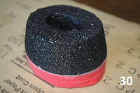
Afterwards you can see there is about a 1/16” vertical swath above the tape. I used some coarse sandpaper and sanded this swath smooth with the cut angle of the band saw. Afterwards, the ear cup mock-up looked like it needed a shave. The sand paper leaves foam filament strands sticking out from the surface (photo 29). The whiskers are easily remedied by applying a little heat from the heat gun to melt the whiskers (photo 30). Be careful you don’t melt your hard work. Start 18” away and slowly brush the heat over your mock-up. You can see the whiskers melt and the foam’s surface tension and color change.
Step 10:

Now back to styro head. I pulled styro head’s aluminum pole from its base and clamped the pole into a bench vise. I positioned the ear cup mock-up over the styro head ear, so the top portion of a human ear (that protrudes the most) would have plenty of upper ear cup room (photo 31). Using a Pen, I carefully drew the outline of the ear cup mock-up onto the masking tape of styro head. I was careful to draw the line just a hair smaller than the actual outline, so it will fit inside the future hole with a slight squeeze.
Step 11:


With a Razor Knife I cut along the ear cup mock-up outline to the full depth (3/4”) of the razor blade (photo 32).
Then starting in the middle of the cut out I cut away chunks of styro until I got to the outline cut. I made sure the hole depth was at least ¾” so the entire swath of red masking tape around the mock-up would fit inside the hole (photo 33).
With a slight squeeze around the perimeter I inserted the ear cup mock-up into the cavity until the top edge of the red masking tape was flush with styro head’s surface (photos 34 and 35).
While the head was still in the vise, I took a hacksaw with a new blade to the ear cup foam. With slow delicate strokes I cut the ear cup foam apex vertical or parallel to the head centerline, from chin to top of head. Note how the top and bottom side taper lengths are different (photos 36 and 37).
Step 12:


Now that the ear cup is in place I can run the final two seam line strings. I’ve marked both of them with the blue ink pen. I also marked where the seam allowance around the ear cup and other local seams would reside (photo 38).
Using pins and string, I marked the final two seams (photo 39).
Step 13:


Using the ¾” masking tape I covered the entire right side of styro head with tape, cut off excess string and removed all the pins (photos 40, 41 and 42).
Step 14:


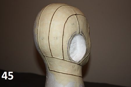
After removing the ear cup mock-up, I used a black marker on the very top of all the masked strings so they can be easily seen thru tissue paper. In addition, I labeled each fabric or leather surface panel I created by the surface divisions of strings. I gave each panel a number and an “R” (Right Side) designation (photos 43, 44 and 45).
Step 15:


Instead of Tracing Paper, I used Tissue Paper normally intended for gift wrapping. It can be found in the gift-wrapping section of a local store. It costs very little, has a strong tensile and you’re not limited to 8 ½” x 11” sheets.
Cut out a large enough piece of Tissue Paper to cover one panel at a time. Use the map pins to hold and stretch the paper over the panel. When most of the wrinkles are out, trace the panel’s marked string / seam lines onto the tissue paper with a pencil (photos 46 and 47).
When complete pull the pins and label the panel number onto the traced tissue paper. Make sure you label on the side traced, not the underside. If you get confused just align the panel and tissue again (photo 48).
Do this step for every panel, plus the ear cup side and top apex panel.
Step 16:
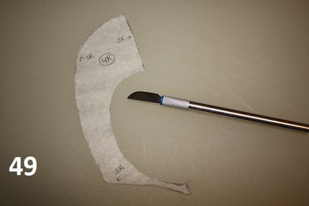
Use a cutting board and razor knife or a pair of scissors to cut out each tissue panel (photo 49).
Step 17:


Tape the tissue panel pattern to a clean wrinkle free piece of copy paper (photo 50). Apply the tape so only a small corner of it holds the tissue to the paper.
Use a blunted pencil to graphite mark the outline of the tissue by repeatedly rubbing in a direction from tissue to copy paper (photo 51). After rub outlining, remove the tape and mark each new panel’s identity and the panel numbers adjacent to its border.
Use the scissors to cut out each copy paper panel (photos 52 and 53).
Step 18:

Now that each panel is composed on a heavier gauge paper, I can start working on cut lines, fold lines, sewing lines and seam allowance. To attach the panels to one another I need to add extra material around the outline of the surface panels that have been created so far.
You need to figure out how you want to assemble and in what order you want to accomplish the assembly of your creation. Hopefully you’ve been thinking about this since you first started running possible seam lines.
If you’re like me and you are more comfortable with building cars than sewing fabric or leather, I highly suggest you take some Instructable Classes. Notably from MikaelaHolmes, such as “Lesson 2: Making Leather Patterns” in her “Intermediate Leather Working Class”. She does an awesome job of explaining these topics and more. So, go get schooled :)
Now that you’re a graduate and have some idea of how to assemble your creation, let’s apply that knowledge to the final pattern making step.
Layout and tape the pattern surface panels on a new sheet of copy paper. Lightly trace the outline of the surface panel onto the new sheet of paper. Use a compass and pencil to mark the outline of the seam allowance (photo 54).
I made my seam allowance ¾” wide, because I have big fingers and it’s tough for me to work with narrow margins. Adjust the allowance for what’s comfortable for you.
After I have a light compass trace of the seam allowance, I un-tape the surface panel and turn it upside down on another sheet of copy paper. Then I tape it to that sheet and make a reverse or mirror copy for the Left side of styro head.
As shown in Photo 54, I used dash lines for the outline of the panels surface and solid lines for the entire cutout (including seam allowance). Then I make notations of which way to fold and/or what panels are adjacent, if it isn’t obvious.
You can also use various computer programs to finish your patterns. With techniques like scanning your panels after Step 17 and then importing them as a vector file into a CAD program. Then you can use vector points and Bezier lines to clean up scissor irregularities on curves and make seam allowances by copying the surface and then up-scaling the copy. A little editing and you have a presentable e-pattern.
Step 19:
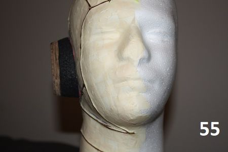


Now it’s time to part ways. This Instructable is about how you can create, using a simple tool and system (photos 55 and 56). My Aviator’s Cap is still an active work in design. My next step is to decide how to run the wires thru the leather piping to the electronic devices (photo 57). I’ll post everything including patterns in another future Instructable.
In the meantime, let’s see what your imagination can manifest into reality.

Third Prize in the
Tape Contest