

Introduction: 3D Printer Cantilever 2.0 C3Dt/c


This is Fourth completed Printer design and third on instructables. Here is the instructions for the C3Dt/c (c for cantilever) by Core3D.tech. This printer was presented at MRRF2018
It is the culmination of many of my other intructables and I will refer/link to those as needed.
The 3D printer is a Cantilever printer with the following features:
- 200mmx200mmx260mm Build volume
- Heated bed
- Auto Bed Leveling using inductive sensor and Aluminum bed
- Linear Rails (MGN12 250mm) on both X and Y axis
- Dedicated Parts cooling
- Runing KFB2.0/Marlin 1.1.9
- BuilkTak Flexplate System
- Bowden Extrusion with BondTech BMG
- 8080 Inc 1010/1020 frame
- Auto tensioning on X and Y Axis
- Double Rod Lead Screw Z axis using 12mm rods for extra stability.
- V6 All metal hotend with cooling adapter for Noctua cooling fan (ultra quiet)
- SD card reader as well as accessible USB port for direct computer access or OctoPrint
All the features you can ask for, in a small and compact build. This printer doesn't just do it all; it looks great doing it.
As an add-on to this instructable, I've created a series of video (10 in total) going through each step of this build. You can find the play list here: Complete Build instructions on video for the C3Dt/c 3D Printer
Here's me chatting with 3D Distributed about the C3Dt/c
All the 3D printed parts that are part of this printer are now available as a set on ebay https://www.ebay.com/usr/core3d.tech
If you are simply looking to get started into 3D Printing, there are many other options available and many cheaper than what I could build this one for (including the rock solid Prusa I3 https://shop.prusa3d.com to which I am not affiliated). So with that out of the way....
If you're patient you can see the entire assembly (down to the last screw) here:
Update 7/30/2018: Some of you seem to have made it through the full build and are requesting information about the Marlin configuration. I've uploaded MY version of the configuration.h today. DO NOT blindly copy this into your set of Marlin files. Parameter names change between versions. I have marked all the changes I made for the C3Dt/c printer with //c3dt/c. Simply search this file for "c3dt" and update your configation.h accordingly (as it applies to the features you have implemented).
Update 1/27/2020: I have since upgraded the C3Dt/c with a bondTech BMG extruder. After having used these on several of my printers, I find it's be best at what it's supposed to do.
Attachments

Step 1: Power Unit Assembly


The C3Dt/c printer is built, around the universal 12 Volt Power switching unit. It's important to get the universal one, as it has all the tapped holes in the exact same positions. This implementation relies on those. It also relies on the Power Unit's cooling fan to force air in the controller unit. Granted, this feature is somewhat experimental as the air coming from the unit is not exactly cold. I still hope this offers better than passive cooling of the controller.
12V 30A DC Universal Regulated Switching Power Supply $18.85 on Amazon https://amzn.to/2r52uRt
For this build the C3Dt/c uses a Power Socket Switch http://amzn.to/2E3Shhathat is 10A fused.
You can clamp wires into the power switch using the tightening screws. If you insert wires directly, DO NOT tin them prior. Not tinning them creates better contact, less chance of them coming loose and thus less chance of arcing (with possible smokey consequences). You can also opt for adding wiring disconnects and fork connectors for proper connections to both Power switch and Power/rocket inlet.
Wiring Quick Disconnects http://amzn.to/2CqLyIx
Fork spade wire connectors http://amzn.to/2F8zcrx
The Electronics case is mounted on top of the Cover (the two holes with square caveties under them). Insert 2 square m3 nuts ( https://amzn.to/2HWYm0P ) into the socket and line them up with the holes. They should fit snug but it could help to add some hot glue after inserting for keeping them in place.
Before finishing up, it's probably a good idea to check if the live wire, really is live. Plugged in and turned on, test with a volt meter (if you're wiring live 110V, you really need to own, and know how to use, one). If you mistakenly swap the Live with Neutral, thing will operate as expected but when you turn off your printer (via switch) power is still present.
Before enclosing the Power unit, run the 12V output wires between the unit and the case. They will end up powering the KFB2.0 (out of sight).
If you plan on adding additional 12 Volt features, it could be handy to add 2 spare +/- wires from remaining slots on the Power unit.
Parts:
- 12V 30A DC Universal Regulated Switching Power Supply 1x
- Power Socket Switch 1x
- Wiring Quick Disconnects 7x (optional)
- Fork spade wire connectors 3x (optional)
- square m3 nuts 6x
- M3 16mm Hex Socket Head x5
Here's the video of this step:


Step 2: Printed Parts


This C3Dt/c consists of about 25 printed components. Yes, I get the irony, a 3D printer is needed to create this 3D printer. Been there, dealt with that by creating a 3D printer design that contains no 3D printed parts whatsoever, added, here on Instructables.com: LAMINATED 3D PRINTER (FROM LASER CUT PARTS ONLY)
All printed pieces are available (as a set only) on eBay https://www.ebay.com/usr/core3d.tech
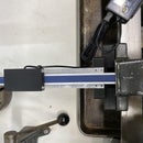
As for the printed parts, not all printers are created equal. My printer creates extremely well fitting pieces around all 1010 extrusions. The image above shows weights hanging on one of the clip on pieces that became a bases for many of the parts. Where extra supports is needed, I've added holes that allow a screw and T-nut for adding additional strength. I did design with shrinkage in mind so all parts are fractions of a millimeter larger than in real life.
Print a few test pieces first, to verify your printer gets similar results as mine. There can be minute dimensional differences between the printer available to you and mine. Also there's expansion/shrinkage of melting/cooling plastics that each has to figure out for themselves (again each printer/process/material has it's own quirks).
Parts of this printer can be printed using PLA (especially pieces like the casing) but I personally prefer PETG. For the pieces close to the extruder and hot end, I PLA will not suffice, due to the high operational temperature. You will need to use PETG or ABS for parts like the Extruder holder/clamp and cooling fan bracket.
The image all Printed Parts above shows the orientation of all pieces on your print bed.
Parts:
See each of the steps that require Printed parts. I've included the STL files there.
Step 3: Z Axis


The Z axis for this implementation is made up from the Linear Screw Double Rail Instructable. Follow the link to that one for more detailed instructions.
The length used for the Z axis is 520mm which allows for a print height of about 290mm (not bad for a cantilever). The minimum length is 495mm but going beyond, allows you to do something extra on top.
I strongly recommend, you use the available screw holes in the Nema Connector and End Connector to screw these components to the rail using t-nuts. The connector can slide up and down depending on pressure applied to them (a failing end-stop may push things out of wack).
The Z Axis design comes with a Z end stop case but since this printer uses Auto bed leveling with a proximity sensor it is not needed.
Before connecting the slider to the Bearing pillows, make sure you drop in 2 10mm (3m) screws through the back of the slider. These will allow you to add t-nuts for extra strength holding the X-Axis.
As for the orientation of the wiring, coming from the Stepper see the image enclosed. For the C2Dt/c Z Axis they point toward the power unit.
Parts:
- 8020 Inc 1010 495mm to 520mm
- Nema 17 Stepper Motor
- Flexible Coupling shaft
- SCS12UU Linear Motion Ball Bearing
- Linear Motion Rod 12 mm x 400mm Shaft
- Lead Screw 8mm
- M5 10mm Hex Socket Head x16
- M3 8mm Hex Socket Head x4
- M3 16mm Hex Socket Head x5
- M3 25mm Hex Socket Head x2
- M3 T-nut 5x
Printed Parts (included with this step):
- Slider12mm.stl
- NemaConnector12mm.stl
- EndConnector12mm.stl
Here's the video for this step:


Step 4: Y Axis


The Y axis will hold the bed and is based of the Generic Linear Actuator with Built-in Tension Spring
VERY IMPORTANT: Before assembling the entire Y Axis, note that it is attached to the frame with a corner plate. Part 3287 (Triple Slide-in Economy T-Nut) needs to be inserted into the rail prior to putting on the nema and idler ends.
The 1010 extrusion should be at least 292mm. Any longer won't make a difference as the Linear rail on top is only 250mm. It dictates the motion range of the slider.
This Axis will be implemented WITH the built-in End stop (As part of the Nema Connector).
The difference with the Generic Linear Rail is the Linear Adapter (LinearAdapterY-Axis.STL) which is customized to hold the Bed Frame.
The Little bracket at the end of the Axis, The LinearRailBreak (at the end of the Linear Rail) is there to prevent the linear rail block to roll of the rails. If that happens the bearing balls can fall out (pain in the .... to get back in).
As for the orientation of the wiring coming from the Stepper see the image enclosed. For the C2Dt/c Y Axis they point toward the Z Axis.
Parts:
- 8020 Inc 1010 292mm
- 8020 Inc Part 3287 1x
- Nema 17 Stepper 1x
- GT2 Timing Belt Pulley 20 Teeth Bore 5mm 1x
- Idler (20 theeth) 3mm bore 1x
- Linear Rail MGN12 250mm 1x
- M3 25mm Hex Socket Head 3x
- M3 16mm Hex Socket Head 2x
- M3 8mm Hex Socket Head 11x (5 at a minimum)
- M3 T-nut 11x (5 at a minimum)
- End Stop (Makerbot style) 1x
- Tension Spring 1x
- GT2 Timing Belt
Printed Parts (included with this step):
- IdlerBracket1010_GT2_20.stl
- BeltGrip.stl
- NemaBracket1010_Endstop.stl
- LinearRailBreak.stl
- LinearAdapterYAxis.stl
Update: If the screw holes in the belt grip are too loose, try the beltgrip_027.STL
Here's the video for this step:


Step 5: X Axis


The X axis will hold the extruder Assembly and is based of the Generic Linear Actuator with Built-in Tension Spring
The 1010 extrusion should be at least 363mm. Any longer won't make a difference as the Linear rail on top is only 250mm. It dictates the motion range of the slider.
This Axis will be implemented WITHOUT the built-in End stop but instead will have a adjustable end stop case.
The difference with the Generic Linear Rail is the Linear Adapter, which will be replaced by the Extruder Clamp (Linear Adapter Extruder Assembly.STL and LinearAdapter Extruder Clamp.stl).
As for the orientation of the wiring coming from the Stepper see the image enclosed. For the C2Dt/c Y Axis they point toward the End-stop case.
Parts:
- 8020 Inc 1010 363mm
- Nema 17 Stepper 1x
- GT2 Timing Belt Pulley 20 Teeth Bore 5mm 1x
- Idler (20 teeth) 3mm bore 1x
- Linear Rail MGN12 250mm 1x
- M3 25mm Hex Socket Head 3x
- M3 16mm Hex Socket Head 3x
- M3 8mm Hex Socket Head 11x (5 at a minimum)
- M3 T-nut 11x (5 at a minimum)
- Tension Spring 1x
- GT2 Timing Belt ~830mm
STL files (included in this step):
- NemaBracket1010_NoEndstop.stl
- IdlerBracket1010_GT2_20.stl
- BeltGrip.stl
- NemaBracket1010
- LinearRailBreak.stl
- LinearAdapter Extruder Assembly.stl
- LinearAdapter Extruder Assembly Clamp.stl
- EndStopCase.stl
Update: If the screw holes in the belt grip are too loose, try the beltgrip_027.STL
Here is the video for this step:
Attachments


Step 6: Assembling the 3D Printer: Frame


Now that the Power switch is wired and enclosed, all axis have been assembled, the frame can be put together.
The frame was designed to "wrap" itself around the 12V power switching unit. It's height of 50mm is extremely close to the height of 1020 extrusion.
There are a few 3D Printed parts that connect the Power Switch unit to the frame. These are not necessarily for support or strength but simply to keep the Power Unit and Electronics in place.
PowerUnit to 1020.stl: 3 M4 6mm
Power to Y Axis.stl: 3 M4 6mm
Power to Y Axis Short: 1 M3 6mm, 1 M4 6mm
The Core support for the Cantilever printer comes from the Corner plates connecting the 1020 (160mm) to both the Z Axis and Y Axis. The 10 Bolts may look like overkill but since this is a cantilever, there's only so many points of support available. The 1020 Rail has two center holes tapped on one.
Please refer to the images on how to assemble the different pieces.
parts:
- 8020 Inc 1020 160mm (One end both holes tapped)
- 8020 Inc Part 3390 15x
- 8020 In Part 4127 1x
- 8020 inc 3287 2x
- 8020 In Part 4151 1x
- 8020 Inc Part 3382 15x
- M4 6mm Hex Socket Head 7x
Printed Parts (included with this step):
- Power To Y Axis.stl
- Power To Y Axis Short.stl
- PowerUnit to 1020.stl
Here's the video for the full assembly:


Step 7: Assembling the 3D Printer: X Axis


The X axis fits (clicks) into the slider of the Z Axis. It can be an extremely tight fit but that's of course for a reason. This will be the heaviest moving part on the printer and you don't want any wiggle room.
I strongly recommend adding the two m3 hex socket screws (10mm) though the back and adding two t-nut in front to further secure the X Axis.
I've left room between the pillow bearing blocks to access these hex sockets screws for tightening.
Word of caution, once the X axis is inserted into the Y Axis it can be challenging to move/remove. Based on my implementation the distance between the X Axis Nema Connector and the Y Axis slider is 4.5mm. The distance from the NemaConnector and the linear Rail is 69.5mm. Do not deviate too much as you want to reach all 4 corners of your print bed as best you can.
Step 8: Assembling the Extruder and Hot-end


The C3Dt/c uses a bowden type extruder which means the stepper pushing the filament through the hot-end is attached to the frame and not directly to the hot-end. This is done to keep the moving mass of the hot-end to a minimum (especially relevant when printing with a cantilever printer).
For the extruder the C3Dt/c printer uses an BondTech BMG https://amzn.to/3aJgWo2 with bowden adapter https://amzn.to/2RvBZmn
The hotend assembly is a e3D all metal V6 with added parts cooling and a proximity sensor. I strongly recommend this part is printed with either PETG or ABS for higher temperature tolerance.
I've added an image of the hot-end with it's loose parts. There's lot of pieces there but I think the image speaks for itself.
When you attach the proximity sensor make sure you mount it close to but slightly higher than the bottom tip of the hot-end (at least by one millimeter). Don't mount it too high as that might push the hot-end into the aluminum bed.
Parts:
- BondTech BMG 1x
- Bondtech Bowden Adapter 1x
- Nema 17 Stepper Motor 1x
- V6 All-Metal HotEnd 1.75mm Universal w/ Bowden Full Kit 12V clone (or better yet, get the real deal from e3d genuine) 1x
- Noctua 40mm fan 1x
- Proximity Sensor Switch LJ12A3-4-Z-BX 1x
- M3 M3 6mm hex socket head 2x
- M3 10mm hex socket head 5x
- M3 16mm hex socket head 4x
- M3 Square Nut 2x
Printed Parts (included with this step)
- ExtruderBracket.stl
- FanAdapterWithPartsCooling.stl
- (parts to connect hot-end to X axis part of the X-axis step)


Step 9: Really Step 8.1: Update to Extruder Assembly


Heaving run the C3Dt/c for a while now I've learned a few things. One of them is that the cooling fan was not properly cooling since air was coming from one direction only. The second thing was the repetitive motion (and strain) on the wires coming from the extruder assembly.
For the cooling I decided to try a new fan that is smaller but packs more punch and for the design I tried to wrap the shroud as much around the nozzle as possible.
For the mini cooling fan assembly I'm using #2 3/8inch srews
The top part of the bracket (minifanAdapter) is connected to the present E3D clamp that holds on to the hot-end by two of the 3/8 Inch screws. The stretched holes allow for upward and downward movement to keep it a few mm above the nozzle tip.
The 40mm fan that cools the extruder heatsink will be attached using the method as shown in https://www.instructables.com/id/30mm-to-40mm-Fan-... using the 30mm_to_40mm_fanAdapter.stl
Parts:
- mini turbo fan 1x
- #2 3/8 inch screws 6x
- m3 hex nuts 4x
- M3 16mm Hex Socket Head x4
- M3 14mm Hex Socket Head x2
- M3 10mm Hex Socket Head x1
- M3 30mm Hex Socket Head x1
Printed Parts (included with this step)
- e3dClamp (to accomodate miniFanAdapter)
- miniFanExhaust.stl
- MiniFanAdapter.stl
- Wire Stabilizer Clamp.stl
- Wire Stabilizer Support.stl
- 30mm_to_40mm_fanAdapter.stl


Step 10: Electronics


For the C3Dt/c printer, I decided to experiment, mounting the electronics case over the Power unit's cooling fan. As it kicks in it blows it's air right over the main board and out the electronics case. It's not exactly active cooling as the air might be warmed up a bit but I believe it might beat passive cooling (no fan on controller at all).
I've not not witnessed any skipped steps or overheating which seems to indicate this is working well.
Keeping the printer compact makes the process of packing all of the electronics inside the case a bit of practice in patience.
For a clean look I've decided to use the Expandable Braided Sleeving (http://amzn.to/2C3sbJZ ) to keep all wiring together.
The large hole at the bottom of the electronics case fits right over the fan exhaust from the power unit. The small hole is to keep all the wiring coming into the case together.
I found it useful to first get all the wiring through the small hole leading them to the bigger compartment to subsequently slide the controller board behind it.
Note: The ventilation slots on top and at the front of the case are very fragile. It works but thin "spokes" break easily. I probable need to re-design this in a way were I can orient the print differently for stronger ventilation holes.
The orientation for the controller speak for itself. The "chips" all point downward and the usb port slides into the square opening at the front of the electronics case.
For the specific wiring of the KFB2.0 I refer you to the instructable WIRING THE KFB2.0 3D PRINTER CONTROLLER
I have also released a full step by step video on how to wire the KFB2.0 for this printer. Check it out here: https://youtu.be/3WxL5Wdu-XY
It, in turn refers to an article I wrote on my blog on how to wire the Proximity sensor at core3d.tech
I've created wire clips that fit around the bundled wires with braided sleeving to keep the wires close to the Z-axis. I personally didn't use more than 3 but you can use more if so wanted.
Parts:
- KFB2.0 (1x)
- Stepper Cables 4x (X/Y/Z/Extruder)
- Stepper Drivers/heat sinks 4x
- 16 gauge wire (red & black)
- Expandable Braided Sleeving
- m3 t-nut 1x
- m3 6mm hex socket head 4x
- m3 10mm hex socket head 2x
Printed Parts (included with this step)
- ElectronicsCase.stl (Updated to have stronger construction)
- WireClip.stl
Here's the video on wiring the KFB2.0 for the C3Dt/c 3D Printer:


Step 11: LCD and SC Card Reader


The C3Dt/c uses a 12864 LCD display with built-in SD Card reader. The case kind of speaks for itself. the LCD fits exactly inside the case and is tied down with 4 m3 6mm screws.
The back of the case has two openings for the 2 ribbon cables that connect the LCD to the KFB2.0
Parts:
Printed Parts (included with this step):
- LCDCase.stl
- LCDLid.stl
- LCDKnob.stl


Step 12: Bed Assembly


Update 8/29/2018: I have recently swapped out the 3D printed bed carriage with an aluminum one with the same dimensions.
Here are a few links to aluminum carriages:
https://www.ebay.com/itm/3DPOWER-ALUMINIUM-Y-carri...
https://www.taralu.net/products/tevo-tarantula-alu...
You can find your own if you search for Tevo Tarantula Y Carriage
This bed comes with pre-drilled holes for the MGN12 rail suggested in this instructable. If you end up using the more compact MGN12 block where holes are 20mm and 15mm spaced, you can special request these holes instead.
The bed carriage for the C3Dt/c is 3D printed which was done purely out of necessity. Ideally you'd want a metal (rigid) frame that is thin. I could not find a 220x220mm metal frame that had screw holes for linear rail block.
The linear adapter on the Y Axis has a large surface to receive the bed frame. Make sure this is smooth. Even the smallest bumps can slant your bed.
For the bed itself I recommend a combination of a aluminum 200mmx200mm (219x219 in actuality) with a silicone heating pad. There's a kit available on ebay at 3D Printer RepRap V2 Aluminum Heated Bed Build Plate /w 12V 200W Heater Full Kit
it comes with scews, bolts and rubber inserts to separate carriage from bed. The bolts will be replaced with regular m3 bolts that will fit inside the sockets underneath the carriage (they should fit snug, but if they fall out, try some glue on the outside of the bolt before inserting).
I also highly recommend going with the BuildTak Flex Plate System. Not only is working do I love their print surfaces (they offer both BuildTak and PEI) but being able to remove the flex plate from the printer is especially beneficial to the printer as the entire bed rests on a single rail block. applying force to remove a print from a mounted bed could wreak havoc on your leveling. You can find the flex plate system here:
https://www.buildtak.com/
For this build you would pick the 8"x8" (original I3) option.
First, attach the carriage with 4 hex socket scews to the Linear Adapter on the Y axis.
Cut the rubber rubber tube to get 4 piece approximately 5-10mm and place (balance) those on the carriage. Next put the Aluminum bed with attached silicone bed (wires pointing towards the back) on top of the rubber connectors and insert screws.
Parts:
Printed Parts (included with this step):
Bed Carriage Printed : Bed Carriage.STL (attached)
Attachments

Step 13: Material List Full


Following is the list of parts used, with links where to get them. I am an Amazon affiliate and if you order through the links below you do end up supporting me with a few dollars (generally, enough to buy new Filament at the end of the month).
You will be able to source many of the items cheaper directly from China via outlets like AliExpress but it will take time and patience to get them.
A quick word about going with Chinese (or for that matter any) knockoffs. I've used many over the last 6 years but, as of today, all my printers use brand products exclusively, they are simply better and worth the extra dollars spent.
8020 Inc Aluminum extrusion (you can get used extrusion on eBay but there's no gaurantee for exact 90 degree angles). I also had some of the items pre-tapped.
I note about links to products. I'm an affiliate with Amazon so where possible I put out links to Amazon.com for 8020 product. Prices on Amazon prime are pretty much in line with direct sales at 8020.net:
8020 Inc.
- 8020 Inc Part 4127 1x Amazon.com
- 8020 In Part 4151 1x Amazon.com
- 8020 Inc 1010 495mm to 520mm 8020.net
- 8020 Inc 1010 292mm 8020.net
- 8020 Inc 1010 363mm 8020.net
- 8020 Inc 1020 160mm (One end both holes tapped) 8020.net
- 8020 inc 3287 3x Amazon.com
- 8020 Inc Part 3282 25x 8020.net
- 8020 Inc Part 3390 15x Amazon.com
Electric
- KFB2.0 1x Amazon.com
- 12V 30A DC Universal Regulated Switching Power Supply 1x Amazon.com
- Aluminum bed 200x200mm with heated silicone pad kit 1x ebay.com
- End Stop (Makerbot style) 1x Amazon.com
- Noctua 40mm fan 1x Amazon.com
- Power Socket Switch 1x Amazon.com
- Proximity Sensor Switch LJ12A3-4-Z-BX 1x Amazon.com
- Stepper Drivers/heat sinks 4x Amazon.com
- V6 All-Metal HotEnd 1.75mm Universal w/ Bowden Full Kit 12V
- clone 1x Amazon.com
- genuine Amazon.com
- Wiring Quick Disconnects 6x (optional) Amazon.com
- Fork spade wire connectors 3x (optional) Amazon.com
- Stepper Cables 4x Amazon.com
- Expandable Braided Sleeving 1/4 inch 25ft Amazon.com
- Nema 17 Stepper 4x Amazon.com
- 16 gauge wire (red & black) Amazon.com
12864 LCD Graphic Smart Display Controller Board Amazon.com
hardware
- Flexible Coupling shaft 1x Amazon.com
- GT2 Timing Belt 5m Amazon.com
- GT2 Timing Belt Pulley 20 Teeth Bore 5mm 2x Amazon.com
- Idler (20 teeth) 3mm bore 2x Amazon.com
- Lead Screw 8mm 1x Amazon.com
- Linear Motion Rod 12 mm x 400mm Shaft 2x McMaster.com
- Linear Rail MGN12 250mm 2x Amazon.com
- BondTech BMG 1x Amazon.com
- BondTech Bowden Adapter 1x Amazon.com
- SCS12UU Linear Motion Ball Bearing 4x Amazon.com
- Tension Spring 2x Amazon.com
- BuilTak FlexPlate System (optional but recommended) BuildTak.com
fasteners
- M3 10mm hex socket head 7x Amazon.com
- M3 16mm Hex Socket Head 19x Amazon.com
- M3 20mm hex socket screws 4x Amazon.com
- M3 25mm Hex Socket Head 8x Amazon.com
- M3 6mm hex socket head 13x Amazon.com
- M3 8mm Hex Socket Head 26x (14 at a minimum) Amazon.com
- M3 hex nuts 4x Amazon.com
- M3 Square Nut 4x Amazon.com
- M3 T-nut 28x (16 at a minimum) Amazon.com
M4 6mm Hex Socket Head x7 Amazon.com
M5 10mm Hex Socket Head x16 Amazon.com
For items purchased directly from 80/20 Inc, consider shipping charges (my orders have been $13.99 shipping/handling) (shipping is included in most Amazon sourced items).
Step 14: Conclusion
I set out to build a Cantilever printer based on a set of universal actuators I designed. I ended up with a 3D printer with all the features the big boys offer (including auto bed leveling). As promised at MRRF2018 the design is now available for all.
The C3Dt/c (Core3D.tech cantilever) is a compact and in my opinion not just functional but also aesthetically pleasing.
Total cost with items sourced from the US lands between $500 and $600.
This instructable should offer you all the steps in recreating this printer. If you're in need of the 3D printed parts, shoot me a message and I'll look into making these available.
In the next few weeks, I'll be adding instructional videos for each step, so come back and check it out.
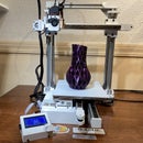
Here it is at work
BTW, if you like what you see and maybe even implement this instructable, consider supporting me on Patreon.com: https://www.patreon.com/Core3d_tech . It took many hours and about as many discarded prototypes to design. Every bit help. Thank you in advance.

Runner Up in the
Make it Move Contest


